

Writing a custom wheel decoder for the Megasquirt
31 Dec 2022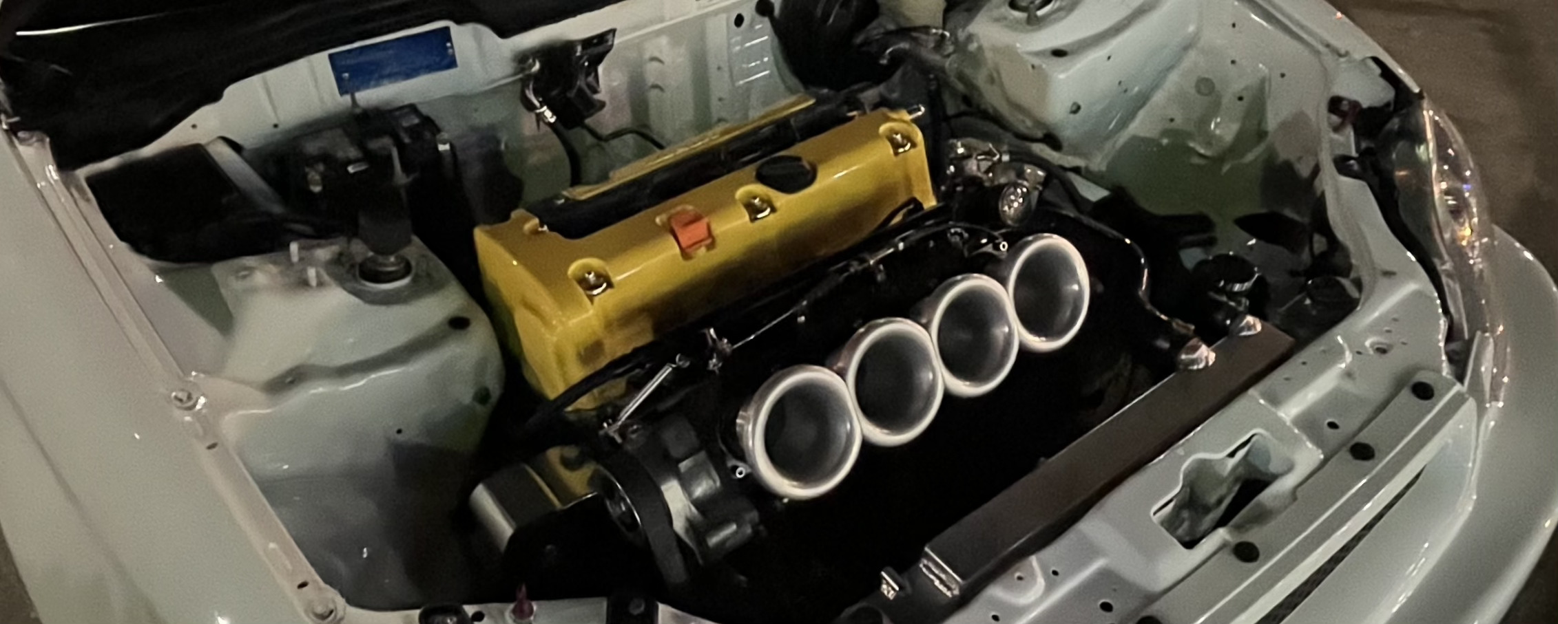
The Megasquirt 2 (2005) become a very successful product down here. The hardware versatility and really low costs for production made it a great management unit for internal combustion engines.
As noted above, the Megasquirt 2 was launched in 2005 and almost 20 years later it’s incredible that it still has new firmware releases, a support forum, and plenty of people to help you with it. Anyways, besides the effort from the developers, the Megasquirt 2 was still missing some interesting stuff I could benefit from, like a wheel decoder for the Honda K20 and K24 engines, the heart of most of the swapped cars we’re running nowadays.
During the early 2000s, Honda developed their awesome K20 and K24 engines. Great, powerful, and solid engines, plenty of torque, and an excellent power band, not to mention that there are extensive catalogs with performance parts to skyrocket the engine power levels.
We usually run these engines on older chassis, such as 1992-2000 Honda Civics, due to their low weight and excellent driveability it’s a no go to swap them from older and weaker 1.6-liter engines to 2.0 or 2.4 beasts that almost double the torque and power.
The problem
While the 90’s Honda electronics are still very tunable, they’re incompatible with the newer engines from Honda: Different trigger wheels, different ignition arrangements, continuously variable cam timing, and so on. Things that the 90’s electronics don’t manage. If the project has enough budget, you could go with an Acura RSX ECU and a Hondata kPro V4 for around $1500, plus a wiring harness ($300-$1000). For us, that’s quite insane in terms of the economy so we go with cheaper solutions that offer at least 95% of the capabilities of the kPro ECU.
The workaround
As stated before, the Megasquirt 2 is a very popular product. It’s cheap and powerful, with plenty of options and configuration but it’s missing a thing: a wheel decoder for the 12+1 trigger wheel that Honda runs on their K20 and K24 engines (among others such as R18 and R20 and some L15s). Since the Megasquirt can decode a missing tooth trigger wheel we convert the stock 12+1 wheel to a 12-1 one, by removing two teeth.
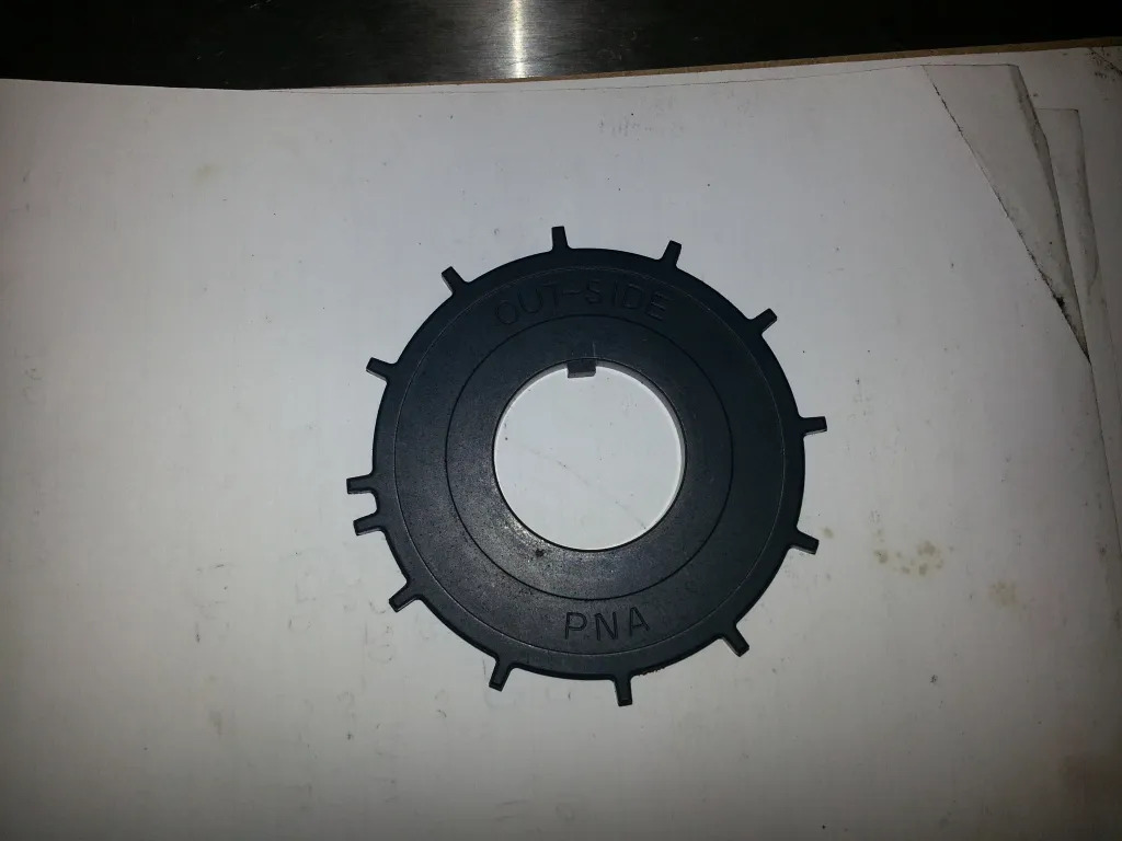
A stock 12+1 trigger wheel from a Honda K-series engine.
To modify the wheel you need to disassemble part of the engine, such as removing the crankshaft pulley, then the timing cover, modify the wheel, reattach everything and pray that the timing cover will not leak oil.
I’ve tuned at least 20 engines with this configuration, by tearing it down into pieces to modify the trigger wheel. Not funny.
The real fix
A few weeks ago I was curious about the Megasquirt 2 firmware source code so I started digging around the Internet for a copy, and hit up a post on msextra.com from one of the developers saying they wouldn’t be releasing the source code anymore, due to the amount of counterfeit MS2 units in the market. Not sure what’s this up to, the compiled firmware is still available to download, hence able to be burnt into any MC9S12C64 CPU and distributed as counterfeit Megasquirt 2 units. Anyways I managed to get a Megasquirt 2 3.4.3 firmware source code copy so I put my hands on it.
Since there’s not much documentation on how the code works, I had to do it the hard way, reading the code and understanding what’s going on on each function, call, and so on. Fortunately, the code is well organized and as it runs on a very old CPU, the instruction set is limited so the code is quite easy to understand.
So there are two files of my interest, ms2_extra_ign_in.c and ms2_extra_ign_wheel.c. One defines the spark modes shown on Tunerstudio, as well as defining some high-level settings of the wheel and the other one is where one gets its hands really dirty: you need to define cycles per degree, number of triggers, number of teeth, trigger angles, and so on.
Research
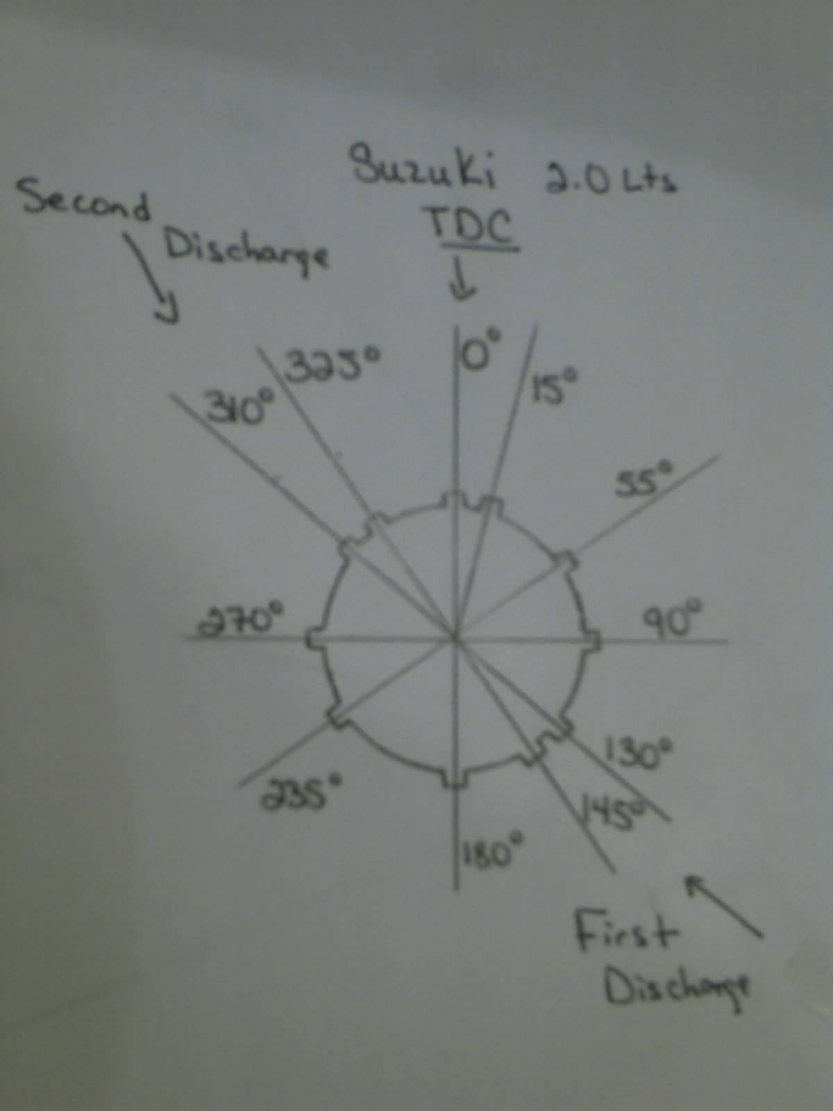
As I had no idea what to look at or touch, I started by doing some research on similar wheel patterns to check how the code works. After some hours I found the Suzuki Vitara 2.0 has a similar trigger wheel pattern.
Interrupt routines
So ms2_extra_ign_in.c is in charge of the interrupt service routines (ISR). Awesome, let’s dive into the SPKMODE18 code block, the one that matches the Suzuki Vitara 2.0 trigger pattern
SPKMODE18:
  //initial sync
  if (!(synch & SYNC_SYNCED)) {
    if  ((!tooth_diff_this) || (!tooth_diff_last) ) {
      return; // only sync when there's enough data
    }
    if (!(synch & SYNC_SEMI)) {
    // look for short tooth after two long ones
      if ( ((tooth_diff_this+(tooth_diff_this>>1)) < tooth_diff_last)
        && ((tooth_diff_this+(tooth_diff_this>>1)) < tooth_diff_last_1) ) {
        tooth_no = 0;
        synch |= SYNC_SEMI;
        } else {
          return;
        }
      } else {
        // semi synced, wait a few teeth
        tooth_no++;
        if (tooth_no < 2) {
          return;
        }
        if ((tooth_diff_this+(tooth_diff_this>>1)) < tooth_diff_last) {
          tooth_no = 2;
          synch |= SYNC_SYNCED;
        } else if (tooth_diff_this > (tooth_diff_last+(tooth_diff_last>>2))) {
          tooth_no = 8;
          synch |= SYNC_SYNCED;
        } else {
          // failed to sync for some reason
          ign_reset();
          return;
        }
      }
  } else {
    // recheck for sync
    if (tooth_no == 11) {  // (one less)
      if ((tooth_diff_this > tooth_diff_last)
        || (tooth_diff_this > tooth_diff_last_1) ) {
        outpc.syncreason = 45;
        ign_reset();
        return;
      } else {
        tooth_no = 0;
      }
    } else if (tooth_no == 6) {  // (one less)
      if ((tooth_diff_this > tooth_diff_last)
        || (tooth_diff_this > tooth_diff_last_1) ) {
        outpc.syncreason = 46;
        ign_reset();
        return;
      }
    }
  }

  goto common_wheel;
Let’s split the code into sections.
Is it synced?
if (!(synch & SYNC_SYNCED)) {
  if  ((!tooth_diff_this) || (!tooth_diff_last) ) {
    return; // only sync when there's enough data
  }
Here, SYNC_SYNCED acts as the flag for the control loop on the wheel decoder, if the engine and ECU are not synced, then try to sync it. Then, if there is no data on the tooth_diff_* variables, that means the control loop hasn’t run yet.
Semi-sequential sync
if (!(synch & SYNC_SEMI)) {
  // look for short tooth after two long ones
  if ( ((tooth_diff_this+(tooth_diff_this>>1)) < tooth_diff_last)
    && ((tooth_diff_this+(tooth_diff_this>>1)) < tooth_diff_last_1) ) {
    tooth_no = 0;
    synch |= SYNC_SEMI;
  } else {
    return;
  }
There’s a flag SYNC_SEMI to set the synch variable to a semi-sequential, wasted-cop state, where injectors and coils fire in pairs. Then walk into tooth_diff_this with a bitwise operator and reset the tooth_no counter if everything is going alright. Also, set synch to SYNC_SEMI with a bitwise OR operator (|=). If there’s no sync yet, just return empty and try again.
Full sync
} else {
  // semi synced, wait a few teeth
  tooth_no++;
  if (tooth_no < 2) {
    return;
  }
  if ((tooth_diff_this+(tooth_diff_this>>1)) < tooth_diff_last) {
    tooth_no = 2;
    synch |= SYNC_SYNCED;
  } else if (tooth_diff_this > (tooth_diff_last+(tooth_diff_last>>2))) {
    tooth_no = 8;
    synch |= SYNC_SYNCED;
  } else {
    // failed to sync for some reason
    ign_reset();
    return;
  }
}
The code waits for a few teeth just for the sake of stability on readings, remember that during the compression periods, the engine speed is reduced due to elevated compression on the piston head, then during exhaust periods the engine goes faster so it’s better to skip a few readings before going full sync.
So if tooth_diff_this and the following bitwise right shift value keep on track, then reset the tooth_no position to 2, and set synch to a new state: SYNC_SYNCED which means it’s fully synced and ready to run. As stated on the wheel pictured above, it may be synced on tooth number 8, meaning it’s the last tooth before a new cycle. If bitwise operators don’t follow the pattern, reset the ignition output with ign_reset() and return empty so the control loop keeps open.
Going forward
} else {
  // recheck for sync
  if (tooth_no == 11) {  // (one less)
    if ((tooth_diff_this > tooth_diff_last)
      || (tooth_diff_this > tooth_diff_last_1) ) {
      outpc.syncreason = 45;
      ign_reset();
      return;
      } else {
        tooth_no = 0;
      }
  } else if (tooth_no == 6) {  // (one less)
    if ((tooth_diff_this > tooth_diff_last)
      || (tooth_diff_this > tooth_diff_last_1) ) {
      outpc.syncreason = 46;
      ign_reset();
      return;
    }
    }
}
Once it’s somewhat synced, just keep track of the tooth difference and return empty (with a loss sync reason number specified) if something is going wrong with the decoder.
Decoding the wheel pattern
The code to the actual decoding happens in ms2_extra_ign_wheel.c. There are else if blocks for each SPKMODE defined in ms2_extra_ign_in.c.
/* ----------------------  Suzuki Vitara 2.0 ------------------------*/
} else if (spkmode == 18) {
  no_teeth = 11;
  last_tooth = no_teeth;
  no_triggers = 4;
  deg_per_tooth[0] =  600;
  deg_per_tooth[1] =  400;
  deg_per_tooth[2] =  700;
  deg_per_tooth[3] =  700;
  deg_per_tooth[4] =  800;
  deg_per_tooth[5] =  400;
  deg_per_tooth[6] =  600;
  deg_per_tooth[7] = 1100;
  deg_per_tooth[8] =  700;
  deg_per_tooth[9] =  800;
  deg_per_tooth[10]=  400;

  smallest_tooth_crk = 400;
  smallest_tooth_cam = 0;

  trigger_teeth[0] = 4;
  trigger_teeth[1] = 7;
  trigger_teeth[2] = 9;
  trigger_teeth[3] = 1;
  trig_angs[0] = -1100 + tmp_offset;
  trig_angs[1] = -1100 + tmp_offset;
  trig_angs[2] = -1100 + tmp_offset;
  trig_angs[3] = -1100 + tmp_offset;
  if (num_cyl !=4) {
    conf_err = 22;
  }
For the Suzuki Vitara, it defines:
no_teethteeth count for the wheel.no_triggerstrigger count, depending on the wheel pattern.deg_per_toothan array to define how many degrees * 10 define each tooth. So 600 = 60 degrees.smallest_tooth_crkandsmallest_tooth_camdefine the position for fully synchronization configuration.trigger_teethis an array to set where in the wheel each trigger for the ignition input.trig_angsangles where the ignition should trigger, negative values mean these are after top dead center angles (ATDC). If ignition triggers BTDC, numbers would be positive.tmp_offsetis the little correction you can make on Tunerstudio to fine-adjust the timing angle with a strobe lamp. This setting goes from -20 to +20 degrees.num_cylis quite self-explanatory, and if it’s not equal to 4, then it returns a configuration error with the number 22.
Based on the msextra post mentioned above, the measurements with the protractor are ported to the deg_pert_tooth array:
  deg_per_tooth[0] =  600;
  deg_per_tooth[1] =  400;
  deg_per_tooth[2] =  700;
  deg_per_tooth[3] =  700;
  deg_per_tooth[4] =  800;
  deg_per_tooth[5] =  400;
  deg_per_tooth[6] =  600;
  deg_per_tooth[7] = 1100;
  deg_per_tooth[8] =  700;
  deg_per_tooth[9] =  800;
  deg_per_tooth[10]=  400;
from the log it looks like it should be
110 // 7
70 // 8
80 // 9
40 // 10
60 // 0
40 // 1
70 // 2
70 // 3
80 // 4
40 // 5
60 // 6
Coding
Now we have a better understanding of how the wheel decoder works, let’s put our hands on it. The first thing is to either define a new SPKMODE or reuse an existing one. I choose the second option because if I want to define a new SPKMODE, I would need to ship a Tunerstudio custom configuration file to make Tunerstudio aware of the new SPKMODE, making the whole process a bit complicated. Digging around the different wheel configurations I ended up using the latest one: Ski-Doo PTEC. Though it may be funny as PTEC sounds like VTEC.
Since this is a crank wheel (not a cam wheel like the Vitara) I had to define a new variable cycle_deg to set up a full 720 degrees cycle (as seen on the crankshaft) and tell the Megasquirt I have twice the teeth (26 instead of 13):
cycle_deg = 7200;
no_triggers = 4;
no_teeth = 26;
deg_per_tooth was set to 30 degrees on each tooth, except for the “+1” arrangement, which is at 10 degrees from the latest tooth and 20 degrees to the following.
Once I had the code completed, it was time to compile it. As I said at the beginning of this post, the Megasquirt 2 launched in 2005, so the development tools are quite old, and most likely the compiler build tools for the Freescale microprocessors won’t run in any up-to-date, modern operating system. I just fired up an old Ubuntu 12.04 x86 virtual machine on my server and quickly installed the build tools.
The compilation succeeded without any errors and I got my .s19 file ready to be burnt into the microprocessor.
Testing on the bench
Testing on the bench was easy: I set up a test Megasquirt 2 box I had lying around there, an Arduino running Ardu-Stim, as my JimStim doesn’t have the 12+1 pattern, and my Hantek oscilloscope.
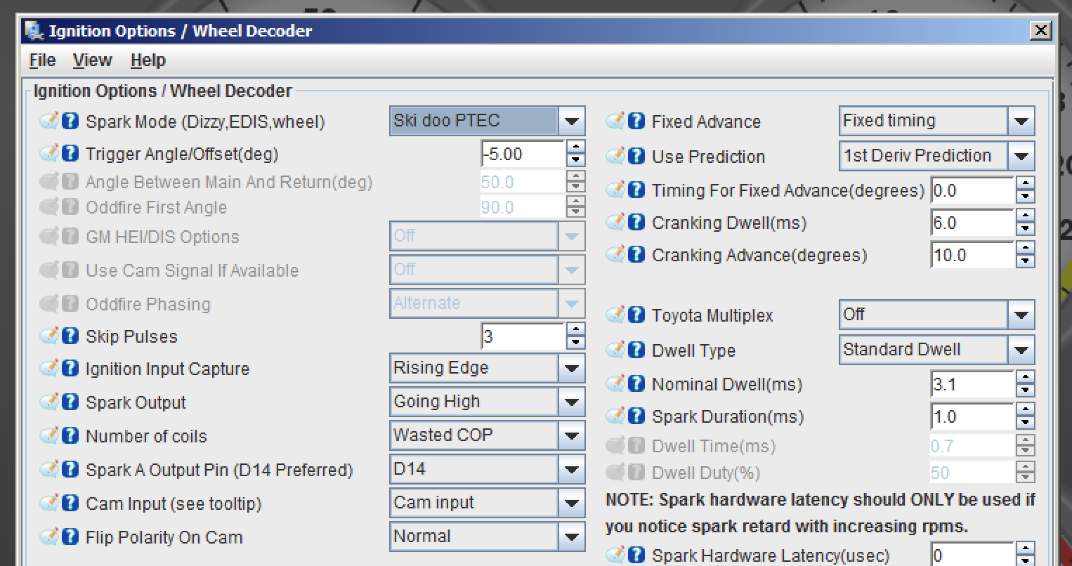
Using the Tunerstudio’s built-in tool to burn firmware, I put my new shiny .s19 file into the Megasquirt unit and configured the toothed wheel as Ski-Doo PTEC. Fired up the Ardu-Stim and bingo!
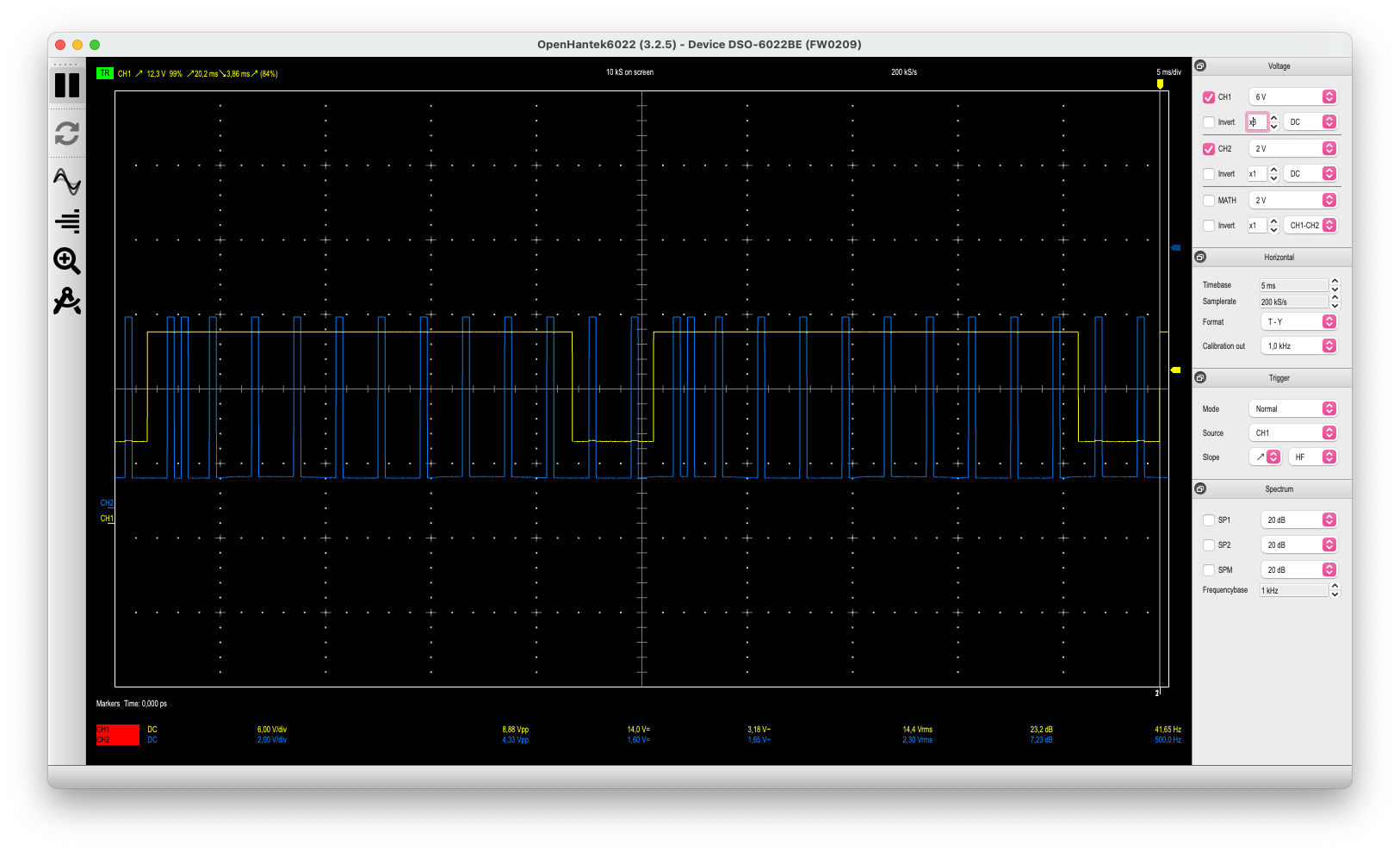
Blue: input trigger signal read from the Arduino. yellow: Channel A ignition output occurring 15 degrees ATDC.
Being checked that the timing was right and the composite logger in Tunerstudio showed up as correct, I decided to talk with my friend Mati to see if we could test it on a real-world engine.
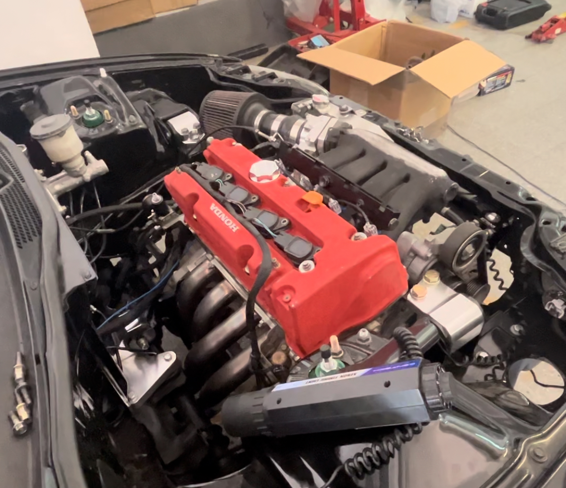
Testing on a real engine
One of my friends, Ale, had his 92’ Honda Civic running a K24 engine with a modified trigger wheel, converted to 12-1 and a Megasquirt 2. Later on, he found a great deal on a low-mileage K20z3 engine, unmolested. Mati suggested that he should keep the original trigger wheel on the K20 engine and then we’ll try the new firmware on it. Once the engine met the car I went to the garage to see if we could fire it up with the custom firmware.
Loaded the new firmware, taking care of disconnecting coils and injectors to avoid unwanted behaviors on the Megasquirt output during the firmware upload, restored the tune, and changed the spark mode from toothed wheel with missing tooth to Ski-Doo PTEC.
During the first try to crank the engine I noticed the timing was way off (by using fixed timing advance to 0 degrees on Tunerstudio). Then I quickly noticed my error: when doing some bench testing I misplaced a 35-degree trig_angs on the firmware. Set it back to the value it had, fired up the Ubuntu 12.04 build VM, built a new .s19 file, and burnt it into the Megasquirt.
Then the engine started quickly, but it sounded like the timing was way off. Double-checked with the timing lamp and, at least, the cylinder 1 timing was perfect. My bad for not checking other cylinders as well!
Back in the bench test, and talking with Mati he told me that cylinders 2 and 3 (output B) had the timing like 30 degrees off. So I set the bench test again, with the oscilloscope probes on outputs A and B:
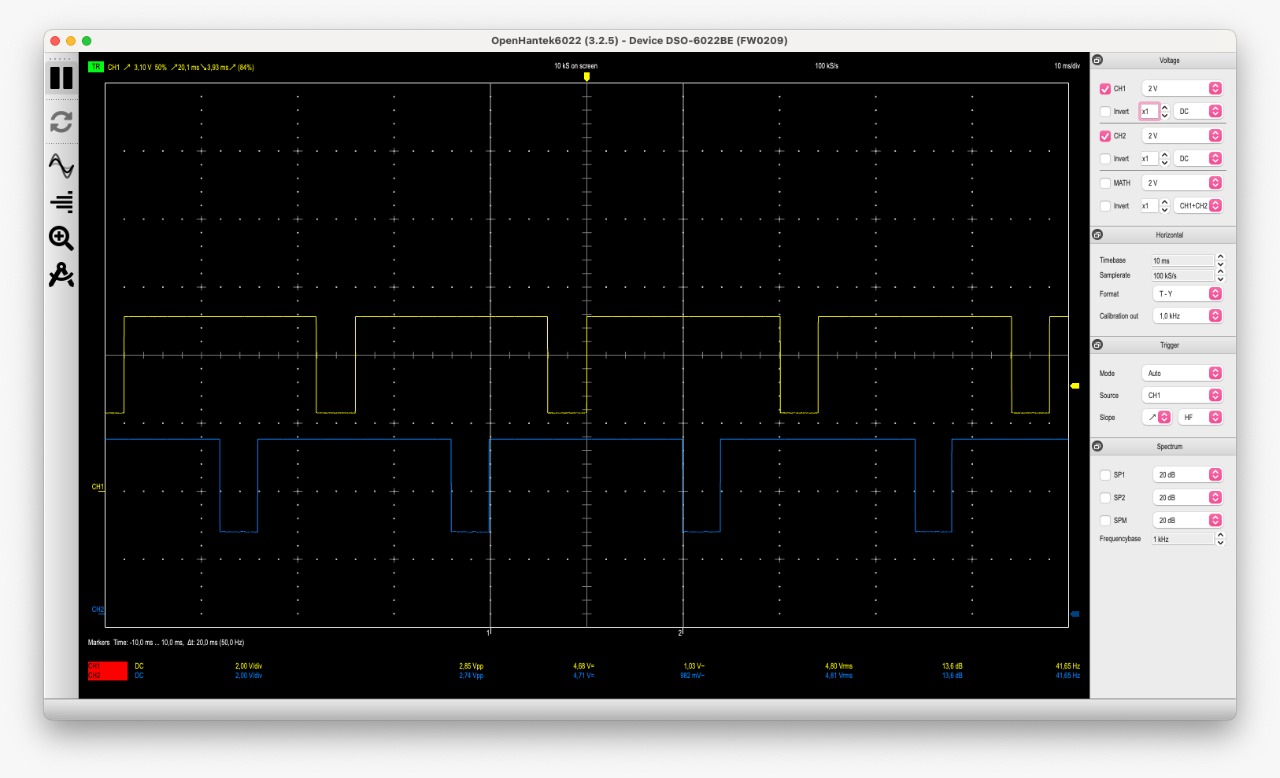
Indeed, you may notice that the traces are a bit off. The yellow trace should be just in the middle of the blue trace. Digging around the code, seemed that the trigger_teeth array was off by 1 tooth, leading to some timing drift between outputs. Correcting the trigger_teeth array values lead to the next oscilloscope sample:
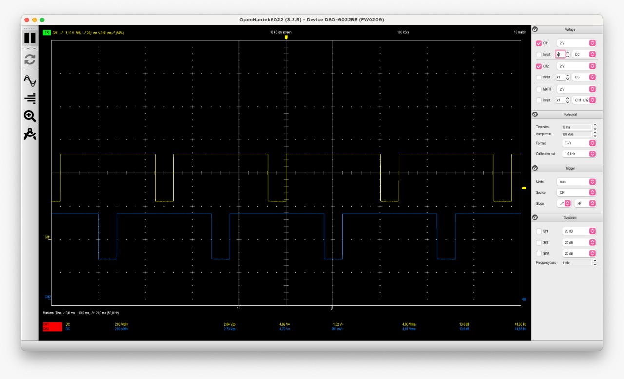
Where traces are now aligned as the engine wanted. Mati then double-checked the timing on all cylinders with this new revision and he could confirm that the timing was the same on the whole engine.
Conclusion
It was really fun to mess around with the wheel decoder, it’s a shame I didn’t mess with it years ago and it’s more shaming that we had to tear down a lot of engines to modify the trigger wheel when the problem could be solved in a couple of hours learning how the Megasquirt did the wheel decoding architecture.
This also opens a very big door for other firmware modifications that we will need to extend the capabilities of our beloved Megasquirt 2. I only hope the Megasquirt developers will post the source code again for the newer releases.
If you’re interested in a copy of the firmware, just fire me an email!