

RadioBerry on a Vertex VX1700
22 Jan 2026A note for the readers: This project is fully documented (from a technical perspective) in reynico/radioberry-setup
Mid last year, my father introduced me to RadioBerry, an open-source FPGA-based Raspberry Pi Hat platform for HF SDR transceivers (0 to 30 MHz). The board uses an AD9866 modem chip and an Intel Cyclone FPGA (CL016 or CL025, depending on the manufacturer) for signal processing.
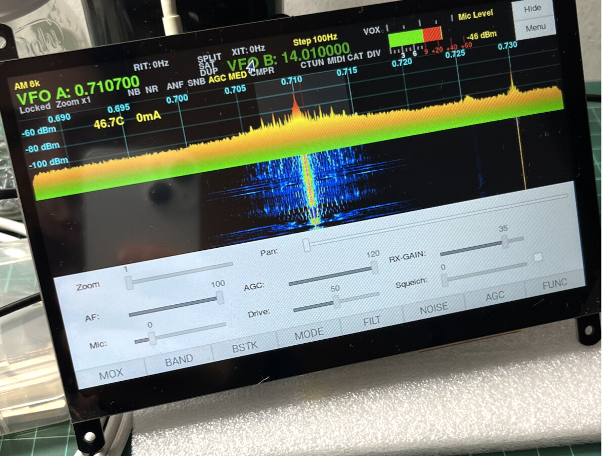
The board outputs a few milliwatts of RF power (100-150mW), enough to drive almost any commercial power amplifier. The recommended control software is PiHPSDR, which packs a lot of features: PA control, low-pass filter board control for band selection, rigctl for Yaesu CAT systems, MIDI controller support for physical interfaces, and a very lengthy list of other capabilities.
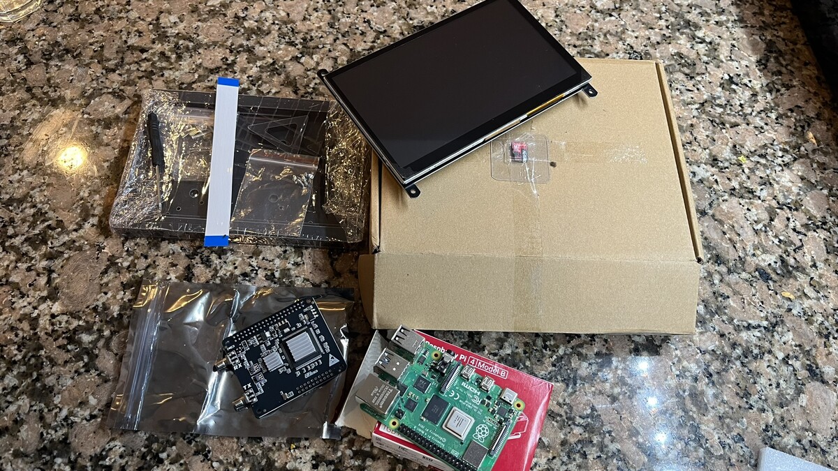
Given that both of us were anxious to try it out, I ordered a complete kit on Aliexpress: 1GB Raspberry Pi 4, SD card, 7” touchscreen display, and the RadioBerry board itself. A few weeks later, the kit arrived, and we started playing with it.
The first thing I tried was tuning in some local AM broadcast stations to see if the thing could actually receive anything. I also made it transmit locally to check the modulation with an SDR dongle. I was surprised by the audio quality, given that I was using a cheap USB soundcard and a lavalier microphone for testing.
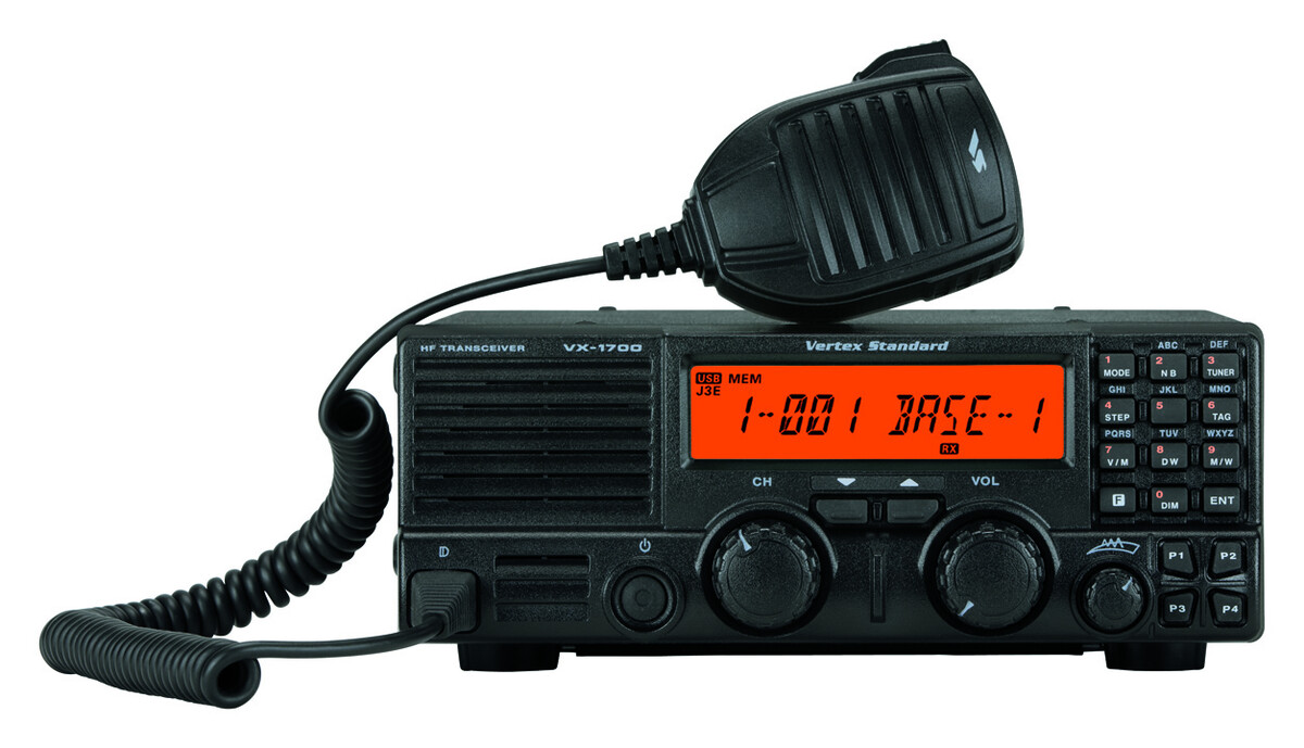
My dad mentioned he had a Vertex Standard (Yaesu) VX1700 HF SSB transceiver that could work for this project. The radio was missing its plastic front panel but otherwise functional. It pushed 100-120 watts of RF power, and the BPF board still worked. This seemed like the perfect foundation: a working amplifier stage with proper filtering, just waiting for a new interface.
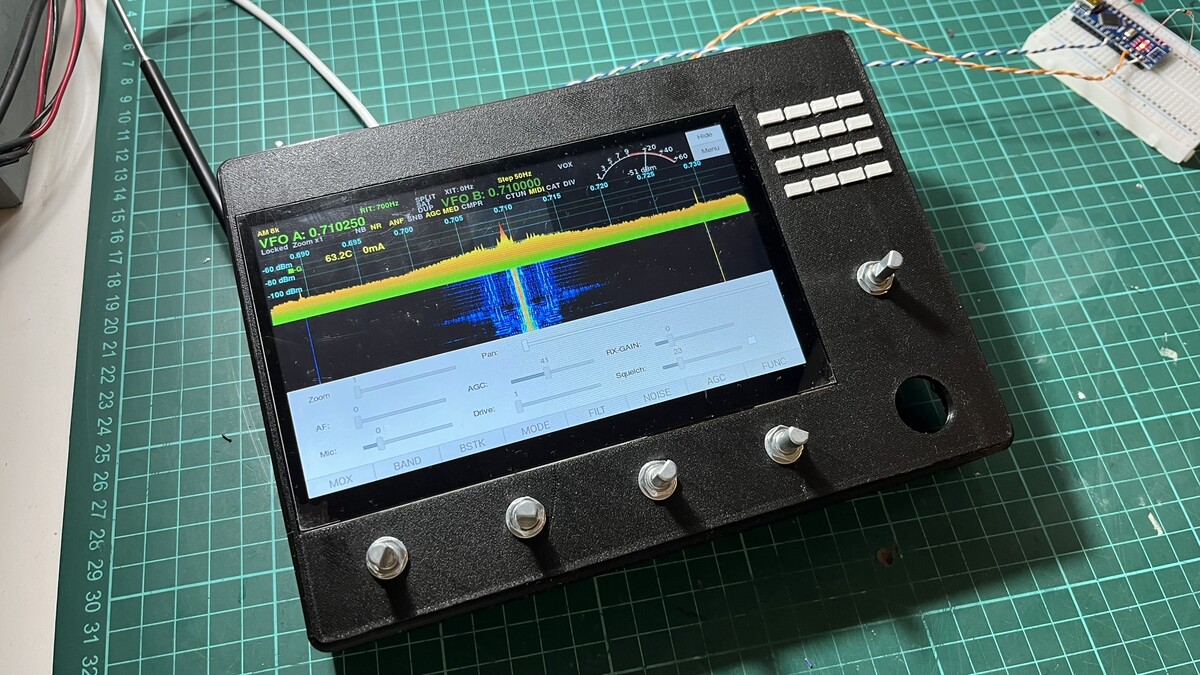
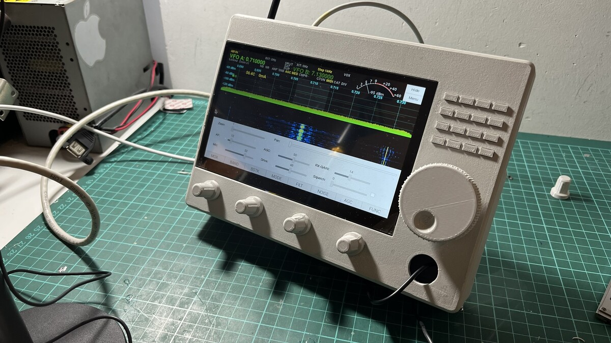
While my dad worked on the radio conversion—removing unneeded components, cleaning up, making RF adjustments—I started designing a 3D printed front panel that could house the 7” display, buttons, and knobs.
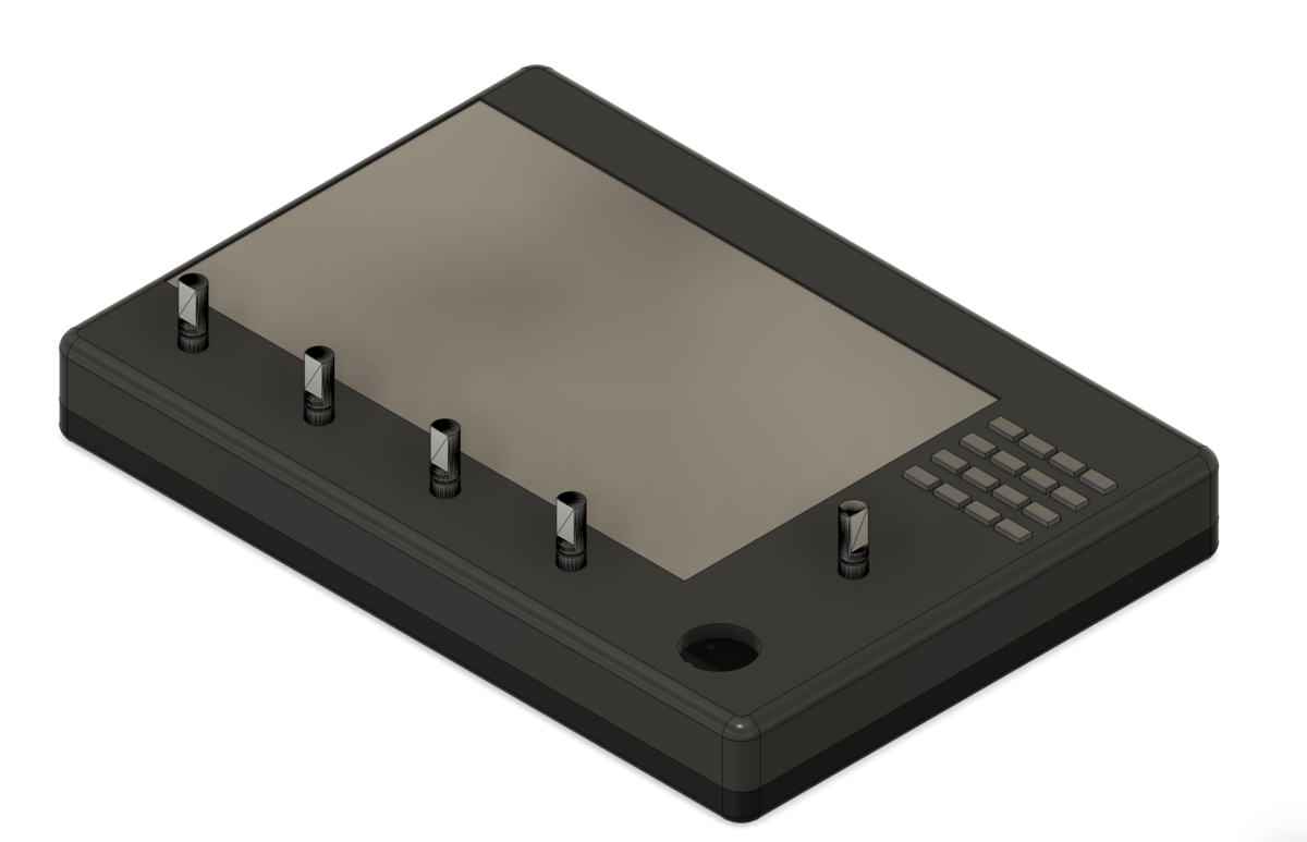
The panel ended up huge due to the screen size. A 5” display probably would have been better suited, but these were our first tests, so we went ahead with what we had. I used five KY-040 rotary encoders with push buttons, a 4x4 matrix keyboard, and a Raspberry Pi Pico RP2040 to emulate MIDI signals. The RP2040 connects to the Raspberry Pi 4 via USB.
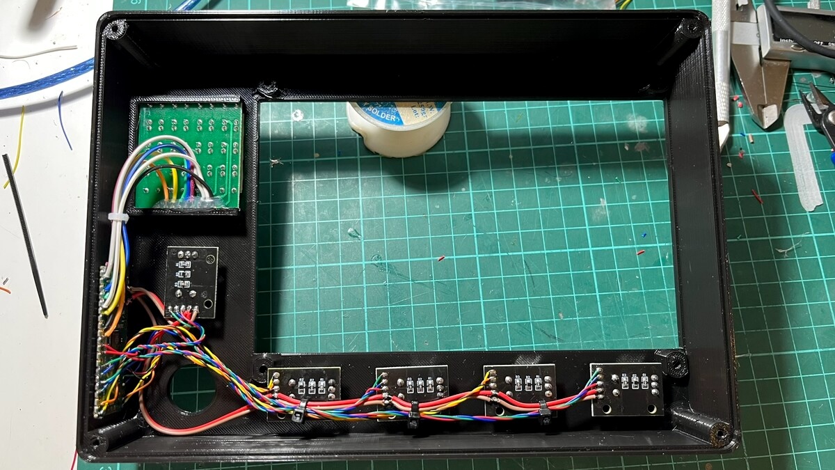
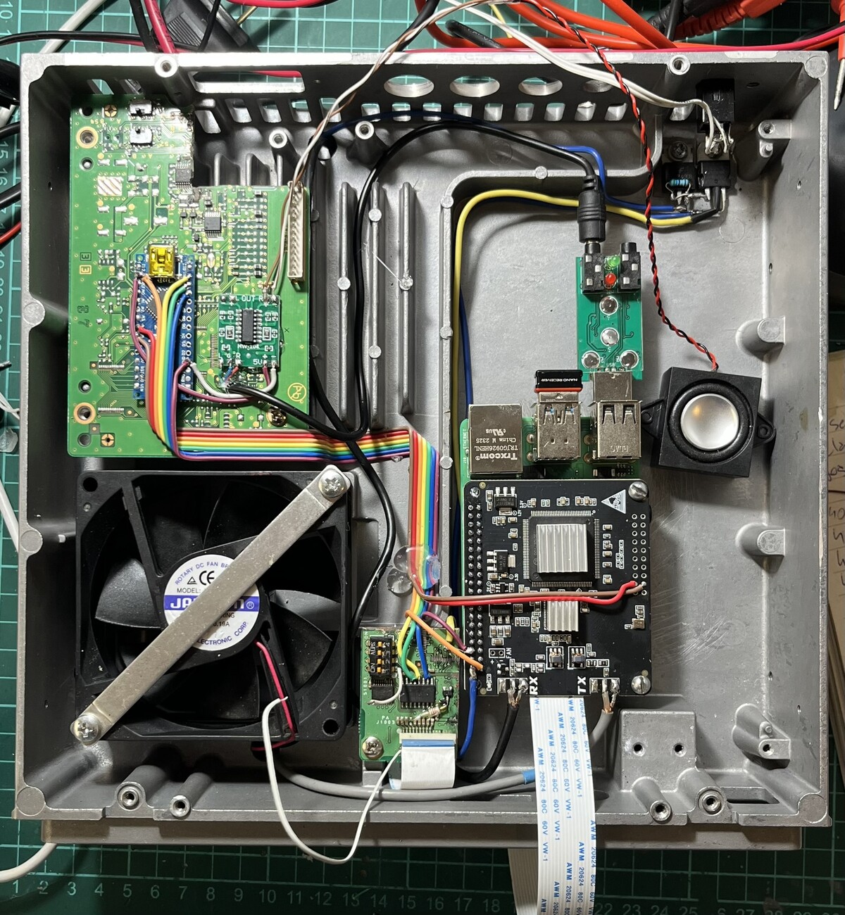
From the operator’s perspective, it looked like this. The big hole down on the right was for the DIN microphone connector. That Arduino Nano in the back controls the BPF board.
And from behind, without the cover:
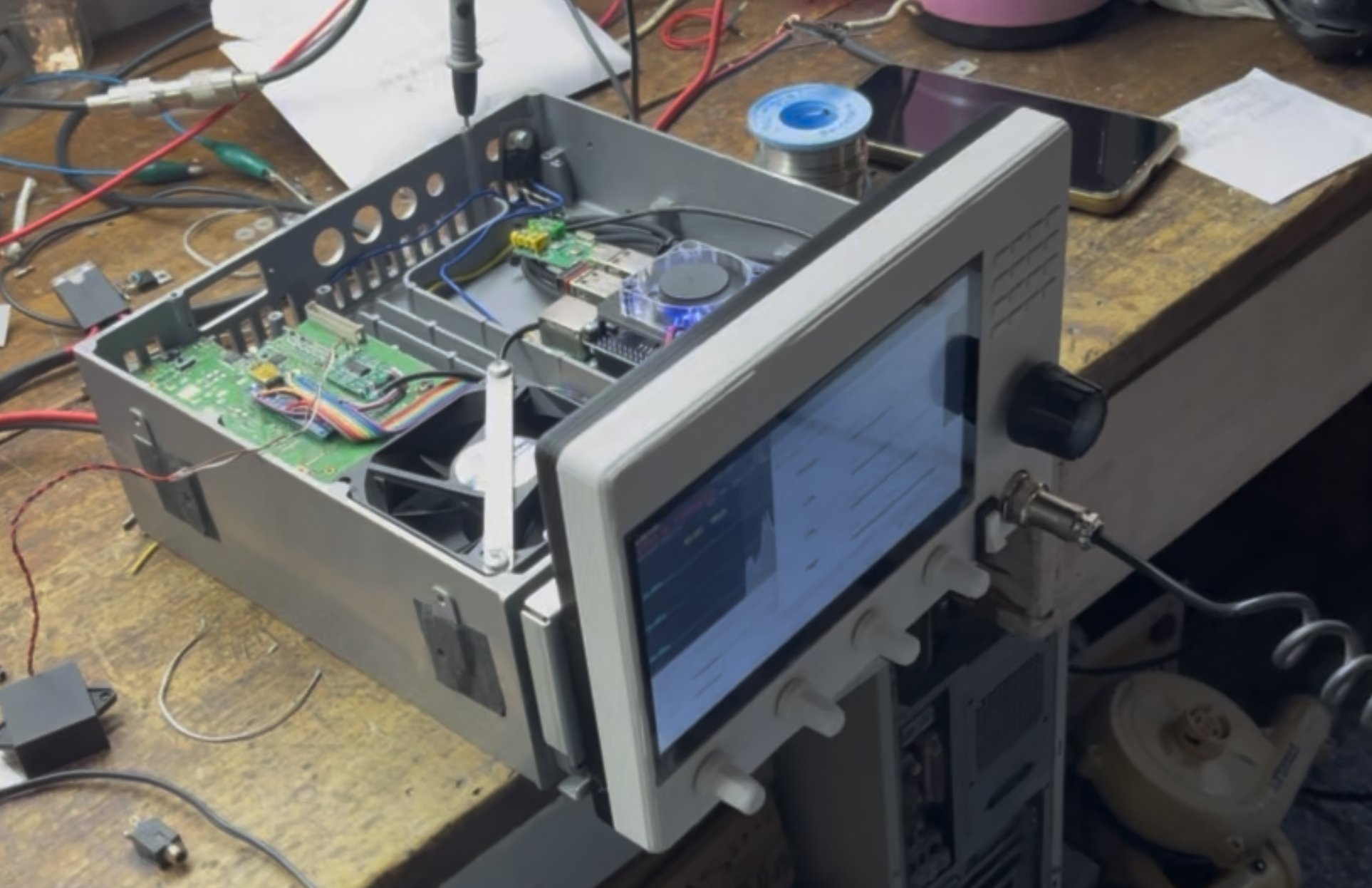
After a few test prints and adjustments—mostly fitting issues, holes that were too small, bad tolerances, the usual 3D printing problems—this was the final result:
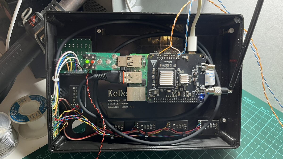
Once the final front panel form was ready, we started putting everything together. The Raspberry Pi is now mounted on the radio, and the Arduino Nano controls the BPF board. The 3D-printed front panel houses the buttons, encoders, display, and RP2040. Between the front panel and the radio, there are only a few wires: microphone, PTT, the display’s flat cable, and the RP2040’s USB cable. You can also see a small speaker, a PAM8403 audio amplifier (I should be used a mono version), and a cheap USB audio interface. Initially, we used the USB audio interface’s speaker output, but it introduced too much noise. We ended up using the Raspberry Pi’s internal speaker jack instead. Now the USB audio card only handles microphone input.
My dad operating the RadioBerry VX1700:
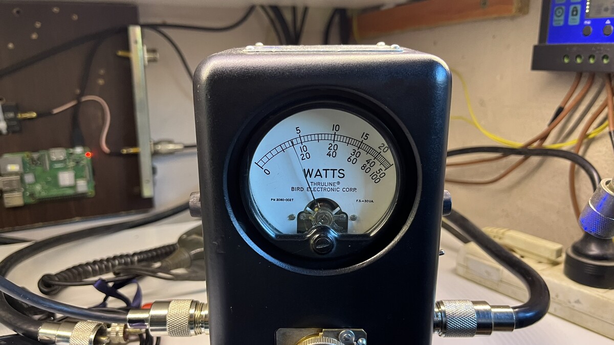
Pushing almost 160W on SSB (1000W element slug):
Controlling the BPF board
The Vertex VX1700 BPF board has 7 built-in filters. Each filter line is enabled through a 12V relay. A Toshiba TD62783AFN 8-channel driver board and a TC4028BF BCD-to-decimal encoder drive the relays. The VX1700’s CPU drives just three data lines.
Since this setup was already working, an Arduino Nano could handle both jobs: emulate an Alex filter board (I2C address 0x21) and control the truth table to drive the TC4028BF, and therefore the filter board.
| Band | Command (Alex board) | C | B | A | Selected filter | Frequency |
|---|---|---|---|---|---|---|
| 160M | 1608 | 0 | 0 | 1 | BPF1 | 1.8 MHz |
| 80M | 1604 | 0 | 1 | 0 | BPF2 | 3.5 MHz |
| 60M | 1602 | 0 | 1 | 1 | BPF3 | 5.3 MHz |
| 40M | 802 | 1 | 0 | 0 | BPF4 | 7 MHz |
| 30M | 401 | 1 | 0 | 1 | BPF5 | 10.1 MHz |
| 20M | 101 | 1 | 1 | 0 | BPF6 | 14 MHz |
| 17M | 164 | 1 | 1 | 0 | BPF6 | 18.1 MHz |
| 15M | 264 | 1 | 1 | 1 | BPF7 | 21 MHz |
| 12M | 4 | 1 | 1 | 1 | BPF7 | 24.9 MHz |
| 10M | 4 | 1 | 1 | 1 | BPF7 | 28 MHz |
Controlling the front panel
To control the front panel knobs and buttons, we used a Raspberry Pi Pico (RP2040), which offers plenty of timers and I/O pins. The front panel comprises five rotary encoders with buttons and a 4x4 keypad matrix.
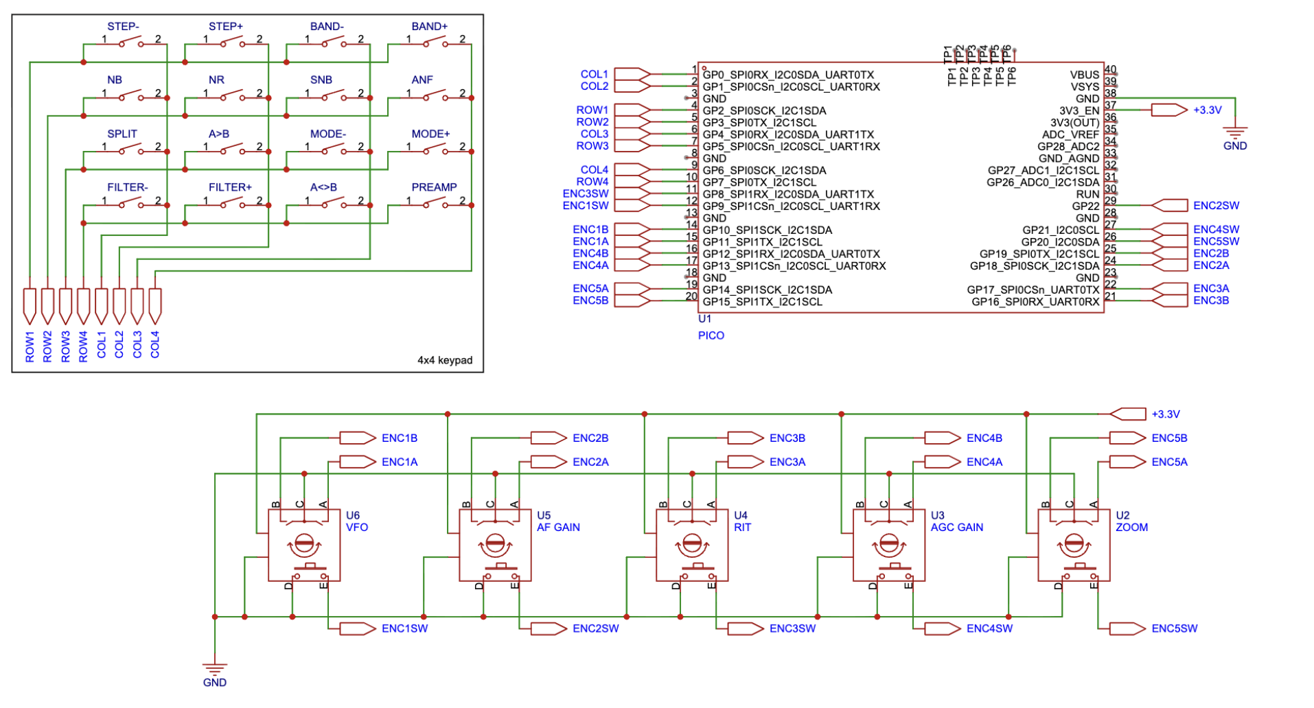
The RP2040 acts as a MIDI controller emulator, reading the electrical signals and converting them to MIDI notes. PiHPSDR supports MIDI as a solution for interfacing in-app buttons with physical controls; you just need to map MIDI notes to actions.
Soft power off
One problem with this implementation: the Raspberry Pi shouldn’t be powered off by simply cutting power. To avoid SD card wear, it’s better to power it off safely through the Raspbian menu or by calling a poweroff command.
The solution is an OR gate circuit. The first gate input comes from a front-panel switch that toggles 5V on or off. That same switch also signals a GPIO pin on the Raspberry Pi (GPIO23). The second gate input is signaled from the Raspberry Pi itself, from GPIO14. GPIO14 goes low when the Raspberry Pi is powered off but still connected to the USB-C power supply. The output of the OR gate connects to an NPN transistor with a large capacitor (3300-4700µF), driving a power relay that shuts down power completely.
This way, if you power off the device from the front-panel switch, the Raspberry Pi is signaled to run poweroff. Once the Raspberry Pi is powered off, both inputs to the OR gate are low, shutting off power to the relay. The large capacitor hooked to the transistor’s base creates a slight delay in powering off the output, giving a few seconds of cooldown to keep things in the safe zone.
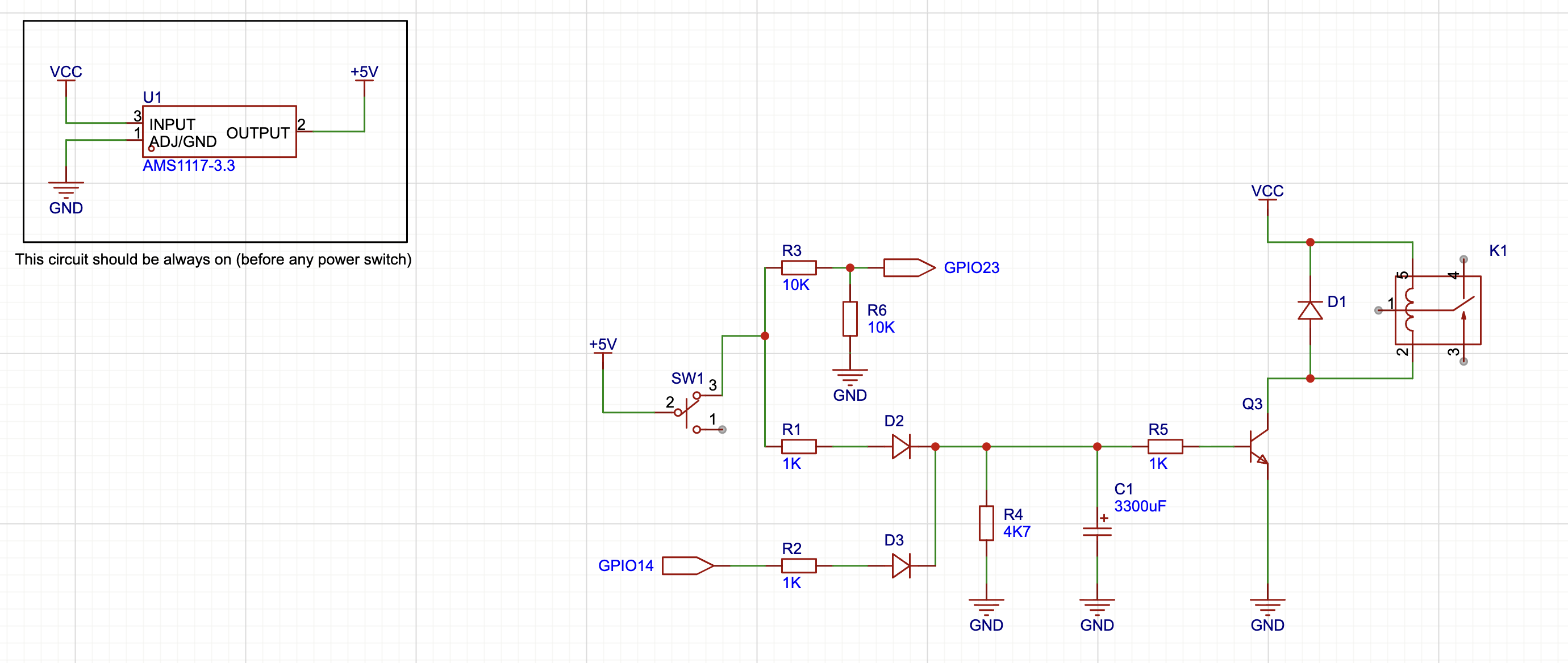
K1 controls the power supply for the Raspberry Pi.
A script runs on the Raspberry Pi in a loop to check whether GPIO23 goes low. Note that if you don’t connect the circuit, you must add a pull-up wire to GPIO23 to avoid shutting down the Raspberry Pi unexpectedly. You’ll need to install gpiod: sudo apt install gpiod
#!/bin/bash

CHIP=gpiochip0
PIN=23
HOLD_TIME_SECONDS=2

gpiomon --num-events=0 --rising-edge --falling-edge $CHIP $PIN | \
while read -r line; do
    if echo "$line" | grep -q "falling edge"; then
        START=$(date +%s.%N)
        while true; do
            VAL=$(gpioget $CHIP $PIN)
            NOW=$(date +%s.%N)
            ELAPSED=$(echo "$NOW - $START" | bc)
            if [ "$VAL" = "1" ]; then
                break
            fi
            if (( $(echo "$ELAPSED >= $HOLD_TIME_SECONDS" | bc -l) )); then
                sudo poweroff
                exit 0
            fi
            sleep 0.05
        done
    fi
done
Conclusion (so far)
This is an ongoing project, so you may find new additions over time. The RadioBerry works well and is highly customizable. However, the RadioBerry itself is just one part of a larger build.
I’m documenting everything I’m learning with the RadioBerry in a GitHub repository. This includes two radios: the Yaesu/Vertex VX1700 shown here and a Yaesu FT-80c I’m still building.