

Simple WAN failover with MikroTik
04 Jan 2024MikroTik offers many options when discussing Internet high availability, ISP redundancy, WAN failover, etc. Some ways are more complex but they offer additional features, and some others are quite straightforward, but wise at the same time. One of my favorites is recursive routing.
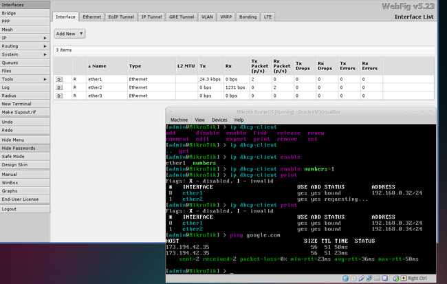
A screenshot I took for a client in 2013, probably testing some sort of WAN load balancing.
I’ll dive you through the internals of recursive routes and a complete working example with two WANs and VLANs for a classic SOHO (Small Office Home Office) setup.
The obvious approach
You could simply define two default routes, the main route will have a smaller metric than the secondary, and that will have the whole traffic routed through 172.16.20.100. If the first interface goes down, the primary route becomes invalid and the traffic will be routed through route number two.
/ip route add gateway=172.16.20.100 distance=1
/ip route add gateway=192.168.1.100 distance=100
but
What happens if the Internet goes down for the main Internet Provider, but its modem (that is 172.16.20.100) keeps online? You bet: Our router will see that route as healthy, and the traffic will be (tried) to be routed on the first gateway. Put in other words, our router will never know when the Internet goes offline if it’s not by the modem getting offline/powered off.
Meet recursive routes
Recursive routes evaluate the WAN reachability to the Internet by weirdly using the following syntax. This could be explained as Traffic going through the default route will be sent to 8.8.8.8, since 8.8.8.8 is not on our network subnet, the routing table will be queried.
/ip route add dst-address=8.8.8.8/32 gateway=172.16.20.100 distance=1 scope=10
If something goes wrong on the main Internet Provider (say, Internet, Modem, wires), 8.8.8.8 won’t be reachable through it. We could also add more reliability to our setup by adding multiple remote hosts, in this case, both remote hosts (8.8.8.8 and 8.8.4.4) need to come down to disable the first route.
/ip route add gateway=8.8.8.8 distance=1 check-gateway=ping
/ip route add gateway=8.8.4.4 distance=1 check-gateway=ping
/ip route add dst-address=8.8.8.8/32 gateway=172.16.20.100 distance=1 scope=10
/ip route add dst-address=8.8.4.4/32 gateway=172.16.20.100 distance=1 scope=10
Caveats
Naturally, the remote hosts are not reachable from the internal network clients. To override this behavior, we need to define a different routing table that doesn’t contain the remote hosts, also, the virtual routes should be present in the main routing tables as well. The complete /ip route example may look like this:
/ip route
add dst-address=8.8.8.8/32 gateway=172.16.20.100 distance=1 routing-table=main scope=10
add dst-address=1.1.1.1/32 gateway=192.168.1.100 distance=1 routing-table=main scope=10
add dst-address=0.0.0.0/0 gateway=8.8.8.8 distance=10 check-gateway=ping routing-table=main scope=30
add dst-address=0.0.0.0/0 gateway=1.1.1.1 distance=11 check-gateway=ping routing-table=main
A SOHO setup
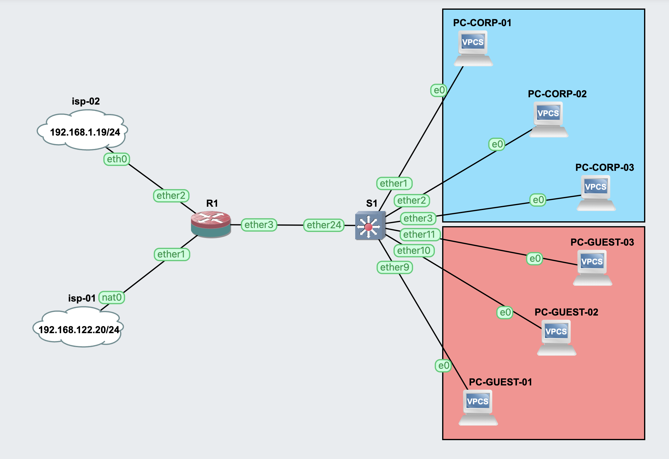
The following SOHO setup features two Internet Providers (main and backup) and two separate VLANs for corporate and guest traffic. The example could be easily extended to meet whatever requirements you may have.
Network Overview
- ISP-01:
- CIDR: 192.168.122.20/24
- Gateway: 192.168.122.1
- ISP-02:
- CIDR: 192.168.1.19/24
- Gateway: 192.168.1.1
- R1: MikroTik router
- ether1: ISP-01 uplink
- ether2: ISP-02 uplink
- ether3: VLAN trunk
- S1: MikroTik switch
- ether1-ether8: VLAN 10 access
- ether9-ether16: VLAN 20 access
- ether24: VLAN trunk
- VLAN 10 (Blue):
- Corporate VLAN
- CIDR: 10.10.10.0/24
- DHCP: 10.10.10.2-10.10.10.254
- VLAN 20 (Red):
- Guest VLAN
- CIDR: 10.10.20.0/24
- DHCP: 10.10.20.2-10.10.20.254
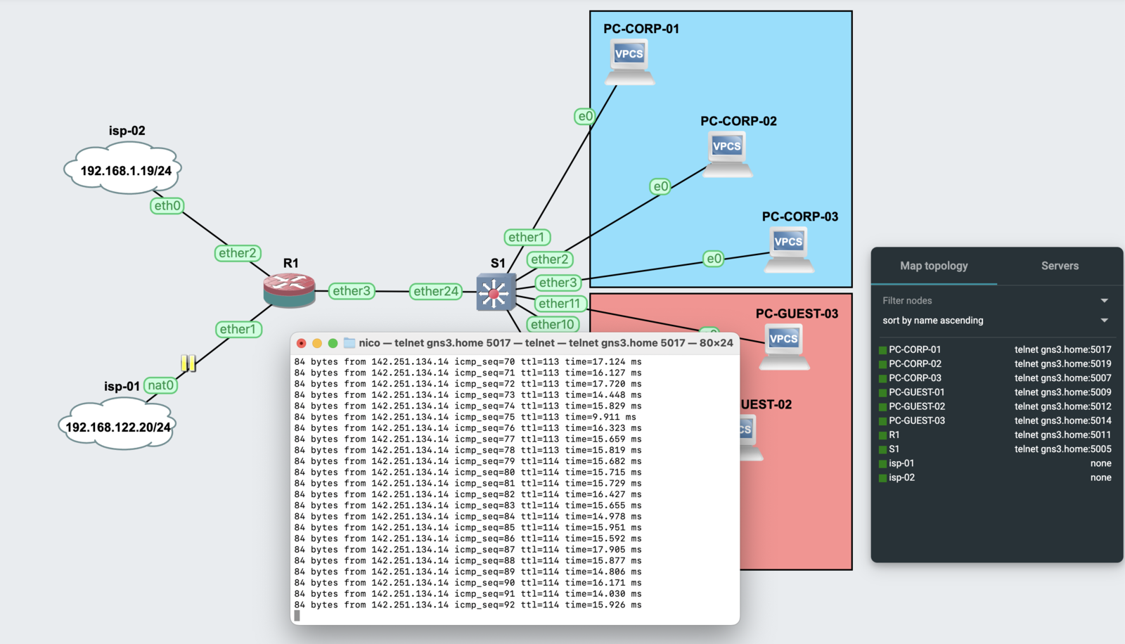
Setting up the lab
This example was built and tested with GNS3, you can download the entire lab from here and import it into your GNS3 instance. I’m using MikroTik CHR 7.7 for both the router and switch. You can download the QEMU images from here.
Router configuration
Interfaces
I started configuring the interfaces on the router. ether1 will be my ISP1 link and ether2 my ISP2 link. Also, a bridge was created in conjunction with two VLANs. For the sake of clarity an interface list for the WAN was created, holding both ISPs’ interfaces into it. Interfaces ether4 and up are disabled.
/interface bridge
add comment="Main bridge" name=Bridge_LAN
/interface ethernet
set [ find default-name=ether1 ] comment=WAN1 disable-running-check=no name=ISP1
set [ find default-name=ether2 ] comment=WAN2 disable-running-check=no name=ISP2
set [ find default-name=ether3 ] disable-running-check=no
set [ find default-name=ether4 ] disable-running-check=no disabled=yes
set [ find default-name=ether5 ] disable-running-check=no disabled=yes
set [ find default-name=ether6 ] disable-running-check=no disabled=yes
set [ find default-name=ether7 ] disable-running-check=no disabled=yes
set [ find default-name=ether8 ] disable-running-check=no disabled=yes
/interface vlan
add comment=Corp interface=Bridge_LAN name=VLAN10 vlan-id=10
add comment=Guest interface=Bridge_LAN name=VLAN20 vlan-id=20
/interface list
add name=WAN
/interface bridge port
add bridge=Bridge_LAN interface=ether3
add bridge=Bridge_LAN interface=ether4
add bridge=Bridge_LAN interface=ether5
add bridge=Bridge_LAN interface=ether6
add bridge=Bridge_LAN interface=ether7
add bridge=Bridge_LAN interface=ether8 pvid=10
/interface list member
add interface=ISP1 list=WAN
add interface=ISP2 list=WAN
IP
IP addresses were defined for the VLAN interfaces and both ISP uplinks
/ip address
add address=192.168.122.20/24 interface=ISP1 network=192.168.122.0
add address=192.168.1.19/24 interface=ISP2 network=192.168.1.0
add address=10.10.10.1/24 interface=VLAN10 network=10.10.10.0
add address=10.10.20.1/24 interface=VLAN20 network=10.10.20.0
add address=10.10.254.1/24 interface=Bridge_LAN network=10.10.254.0
Three DHCP pools were created, management, corporate, and guest networks. Just for simplicity, I’m using the same public DNS servers for all VLANs and the router.
/ip pool
add comment=Management name=dhcp_pool_mgmt ranges=10.10.254.2-10.10.254.254
add comment=Corp name=dhcp_pool_corp ranges=10.10.10.2-10.10.10.200
add comment=Guest name=dhcp_pool_guest ranges=10.10.20.2-10.10.20.200

/ip dhcp-server
add address-pool=dhcp_pool_mgmt comment=Management interface=Bridge_LAN name=Bridge_LAN
add address-pool=dhcp_pool_corp comment=Corp interface=VLAN10 lease-time=5m name=VLAN10
add address-pool=dhcp_pool_guest comment=Guest interface=VLAN20 lease-time=5m name=VLAN20

/ip dhcp-server network
add address=10.10.10.0/24 comment=Corp dns-server=8.8.8.8,1.1.1.1 gateway=10.10.10.1
add address=10.10.20.0/24 comment=Guest dns-server=8.8.8.8,1.1.1.1 gateway=10.10.20.1
add address=10.10.254.0/24 dhcp-option=*1 dns-server=8.8.8.8,1.1.1.1 gateway=10.10.254.1

/ip dns
set servers=8.8.8.8,8.8.4.4
Routing
The routing was detailed in the previous section of this post
/ip route
add comment=CheckDNS-ISP1 disabled=no distance=1 dst-address=8.8.8.8/32 gateway=192.168.122.1 pref-src="" routing-table=main scope=10
add comment=CheckDNS-ISP2 disabled=no distance=1 dst-address=1.1.1.1/32 gateway=192.168.1.1 pref-src="" routing-table=main scope=10
add check-gateway=ping comment=DefaultRoute-ISP1 disabled=no distance=10 dst-address=0.0.0.0/0 gateway=8.8.8.8 pref-src=0.0.0.0 routing-table=main scope=30
add check-gateway=ping comment=BackupRoute-ISP2 disabled=no distance=11 dst-address=0.0.0.0/0 gateway=1.1.1.1 pref-src=0.0.0.0 routing-table=main
Firewall, NAT, and mangle
I am filtering out the router management requests that could come from both WAN ports or the guest VLAN port, there are also two rules to drop inter-VLAN traffic.
Mangle is there just to mark connections and routes for both ISPs and the NAT masquerades whatever WAN traffic appears.
/ip firewall filter
add action=drop chain=input comment="Block Management - VLAN20" dst-port=22,23,8291,80,443 in-interface=VLAN20 protocol=tcp
add action=drop chain=input comment="Block Management - ISP1" dst-port=22,23,8291,80,443 in-interface=ISP1 protocol=tcp
add action=drop chain=input comment="Block Management - ISP2" dst-port=22,23,8291,80,443 in-interface=ISP2 protocol=tcp
add action=accept chain=input comment="Allow Management - Local Network" dst-port=80,8291,22 in-interface=Bridge_LAN protocol=tcp
add action=drop chain=forward comment="Block inter-vlan traffic" dst-address=10.10.20.0/24 src-address=10.10.10.0/24
add action=drop chain=forward comment="Block inter-vlan traffic" dst-address=10.10.10.0/24 src-address=10.10.20.0/24

/ip firewall mangle
add action=mark-connection chain=prerouting connection-state=new in-interface=ISP1 new-connection-mark=ISP1_conn
add action=mark-connection chain=prerouting connection-state=new in-interface=ISP2 new-connection-mark=ISP2_conn
add action=mark-routing chain=output connection-mark=ISP1_conn new-routing-mark=To_ISP1
add action=mark-routing chain=output connection-mark=ISP2_conn new-routing-mark=To_ISP2

/ip firewall nat
add action=masquerade chain=srcnat out-interface-list=WAN
Complete configuration
The complete router configuration is next here, it may be easy for you just to copy and paste the whole configuration into your router and then adjust the required parameters.
# jan/04/2024 20:16:07 by RouterOS 7.7
# software id =
#
/interface bridge
add comment="Main bridge" name=Bridge_LAN
/interface ethernet
set [ find default-name=ether1 ] comment=WAN1 disable-running-check=no name=ISP1
set [ find default-name=ether2 ] comment=WAN2 disable-running-check=no name=ISP2
set [ find default-name=ether3 ] disable-running-check=no
set [ find default-name=ether4 ] disable-running-check=no disabled=yes
set [ find default-name=ether5 ] disable-running-check=no disabled=yes
set [ find default-name=ether6 ] disable-running-check=no disabled=yes
set [ find default-name=ether7 ] disable-running-check=no disabled=yes
set [ find default-name=ether8 ] disable-running-check=no disabled=yes
/interface vlan
add comment=Corp interface=Bridge_LAN name=VLAN10 vlan-id=10
add comment=Guest interface=Bridge_LAN name=VLAN20 vlan-id=20
/interface list
add name=WAN
/interface wireless security-profiles
set [ find default=yes ] supplicant-identity=MikroTik
/ip pool
add comment=Management name=dhcp_pool_mgmt ranges=10.10.254.2-10.10.254.254
add comment=Corp name=dhcp_pool_corp ranges=10.10.10.2-10.10.10.200
add comment=Guest name=dhcp_pool_guest ranges=10.10.20.2-10.10.20.200
/ip dhcp-server
add address-pool=dhcp_pool_mgmt comment=Management interface=Bridge_LAN name=Bridge_LAN
add address-pool=dhcp_pool_corp comment=Corp interface=VLAN10 lease-time=5m name=VLAN10
add address-pool=dhcp_pool_guest comment=Guest interface=VLAN20 lease-time=5m name=VLAN20
/port
set 0 baud-rate=115200 name=serial0
set 1 baud-rate=115200 name=serial1
/routing table
add disabled=no fib name=To_ISP1
add disabled=no fib name=To_ISP2
add disabled=no fib name=ISP1_conn
add disabled=no fib name=ISP2_conn
/snmp community
set [ find default=yes ] disabled=yes
/interface bridge port
add bridge=Bridge_LAN interface=ether3
add bridge=Bridge_LAN interface=ether4
add bridge=Bridge_LAN interface=ether5
add bridge=Bridge_LAN interface=ether6
add bridge=Bridge_LAN interface=ether7
add bridge=Bridge_LAN interface=ether8 pvid=10
/ip neighbor discovery-settings
set discover-interface-list=!dynamic
/ip settings
set max-neighbor-entries=16384
/ipv6 settings
set max-neighbor-entries=16384
/interface list member
add interface=ISP1 list=WAN
add interface=ISP2 list=WAN
/ip address
add address=10.10.254.1/24 interface=Bridge_LAN network=10.10.254.0
add address=10.10.10.1/24 interface=VLAN10 network=10.10.10.0
add address=192.168.1.19/24 interface=ISP2 network=192.168.1.0
add address=192.168.122.20/24 interface=ISP1 network=192.168.122.0
add address=10.10.20.1/24 interface=VLAN20 network=10.10.20.0
/ip cloud
set update-time=yes
/ip dhcp-server network
add address=10.10.10.0/24 comment=Corp dns-server=8.8.8.8,1.1.1.1 gateway=10.10.10.1
add address=10.10.20.0/24 comment=Guest dns-server=8.8.8.8,1.1.1.1 gateway=10.10.20.1
add address=10.10.254.0/24 dhcp-option=*1 dns-server=8.8.8.8,1.1.1.1 gateway=10.10.254.1
/ip dns
set servers=8.8.8.8,8.8.4.4
/ip firewall filter
add action=drop chain=input comment="Block Management - VLAN20" dst-port=22,23,8291,80,443 in-interface=VLAN20 protocol=tcp
add action=drop chain=input comment="Block Management - ISP1"  dst-port=22,23,8291,80,443 in-interface=ISP1 protocol=tcp
add action=drop chain=input comment="Block Management - ISP2" dst-port=22,23,8291,80,443 in-interface=ISP2 protocol=tcp
add action=accept chain=input comment="Allow Management - Local Network" dst-port=80,8291,22 in-interface=Bridge_LAN protocol=tcp
add action=drop chain=forward comment="Block inter-vlan traffic" dst-address=10.10.20.0/24 src-address=10.10.10.0/24
add action=drop chain=forward comment="Block inter-vlan traffic" dst-address=10.10.10.0/24 src-address=10.10.20.0/24
/ip firewall mangle
add action=mark-connection chain=prerouting connection-state=new in-interface=ISP1 new-connection-mark=ISP1_conn
add action=mark-connection chain=prerouting connection-state=new in-interface=ISP2 new-connection-mark=ISP2_conn
add action=mark-routing chain=output connection-mark=ISP1_conn new-routing-mark=To_ISP1
add action=mark-routing chain=output connection-mark=ISP2_conn new-routing-mark=To_ISP2
/ip firewall nat
add action=masquerade chain=srcnat out-interface-list=WAN
/ip route
add comment=CheckDNS-ISP1 disabled=no distance=1 dst-address=8.8.8.8/32 gateway=192.168.122.1 pref-src="" routing-table=main scope=10
add comment=CheckDNS-ISP2 disabled=no distance=1 dst-address=1.1.1.1/32 gateway=192.168.1.1 pref-src="" routing-table=main scope=10
add check-gateway=ping comment=DefaultRoute-ISP1 disabled=no distance=10 dst-address=0.0.0.0/0 gateway=8.8.8.8 pref-src=0.0.0.0 routing-table=main scope=30
add check-gateway=ping comment=BackupRoute-ISP2 disabled=no distance=11 dst-address=0.0.0.0/0 gateway=1.1.1.1 pref-src=0.0.0.0 routing-table=main
/system identity
set name=R1
Switch configuration
The switch is in its most plain and basic setup, it just does basic VLAN switching. I’ll not go into the deeper details of the configuration as it just does switching from the trunk to the access ports.
# jan/04/2024 20:26:14 by RouterOS 7.7
# software id =
#
/interface bridge
add name=bridge1 vlan-filtering=yes
/interface vlan
add interface=bridge1 name=mgmt vlan-id=99
/port
set 0 name=serial0
/interface bridge port
add bridge=bridge1 interface=ether24
add bridge=bridge1 interface=ether1 pvid=10
add bridge=bridge1 interface=ether2 pvid=10
add bridge=bridge1 interface=ether3 pvid=10
add bridge=bridge1 interface=ether4 pvid=10
add bridge=bridge1 interface=ether5 pvid=10
add bridge=bridge1 interface=ether6 pvid=10
add bridge=bridge1 interface=ether7 pvid=10
add bridge=bridge1 interface=ether8 pvid=10
add bridge=bridge1 interface=ether9 pvid=20
add bridge=bridge1 interface=ether10 pvid=20
add bridge=bridge1 interface=ether11 pvid=20
add bridge=bridge1 interface=ether12 pvid=20
add bridge=bridge1 interface=ether13 pvid=20
add bridge=bridge1 interface=ether14 pvid=20
add bridge=bridge1 interface=ether15 pvid=20
add bridge=bridge1 interface=ether16 pvid=20
/interface bridge vlan
add bridge=bridge1 tagged=ether24 untagged=ether1,ether2,ether3,ether4,ether5,ether6,ether7,ether8 vlan-ids=10
add bridge=bridge1 tagged=ether24 untagged=ether9,ether10,ether11,ether12,ether13,ether14,ether15,ether16 vlan-ids=20
add bridge=bridge1 tagged=ether24,bridge1 vlan-ids=99
/system identity
set name=S1
Tests
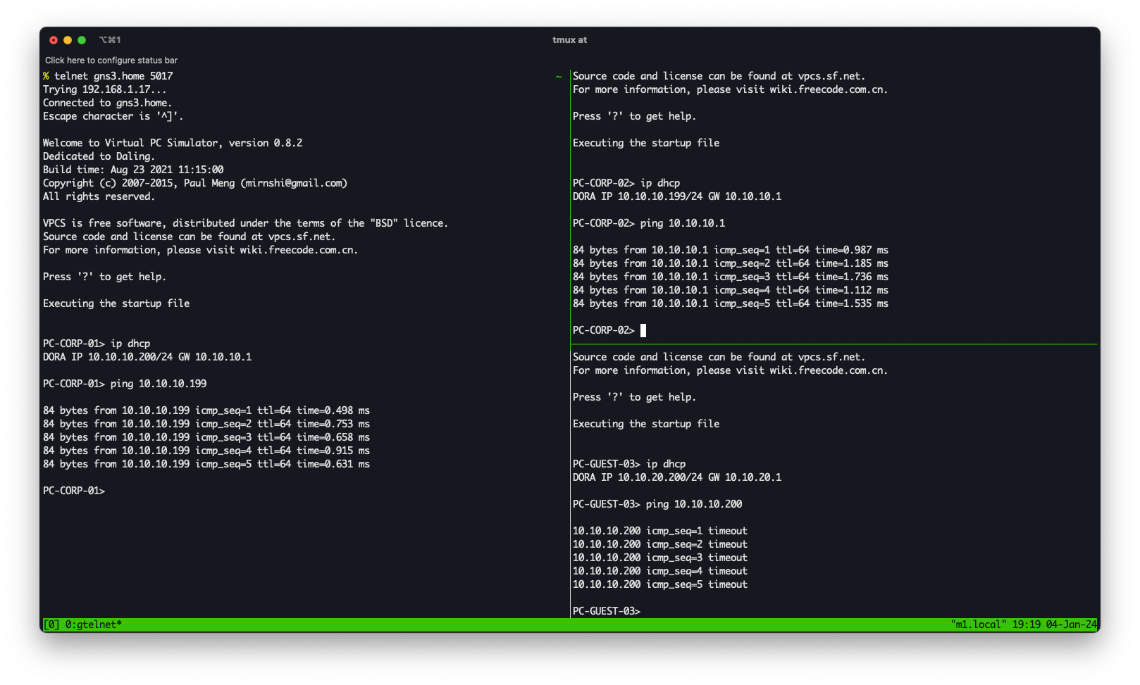
Let’s do some tests by telneting into our virtual PCs. The first thing we need to do after we log into the virtual PC is to assign an IP address, hopefully, the DHCP server configured for our VLAN will do the job for us. Issuing ip dhcp the virtual PC will try to get an IP address from the gateway.
PC-CORP-01> ip dhcp
DORA IP 10.10.10.200/24 GW 10.10.10.1
Failover
By suspending the network link between one of the ISPs and the router, the failover solution acts immediately, so fast that the ping from one of the virtual PCs never notices the problem
Inter-VLAN Connectivity
Due to the firewall rules that prevent inter-VLAN connectivity, PC-GUEST-03 cannot reach any of the corporate computers, while inter-corporate communications are allowed
Future work
There’s a lot of room for improvement here, but they are out-of-scope for this post. Some stuff that comes to my mind right now are:
- Failover with WAN load balancing, to take advantage of the extra bandwidth.
- A detailed firewall configuration, with stricter rules.
- Network monitoring with an IDS/IPS.
- High availability or failover on the router and switch stages.