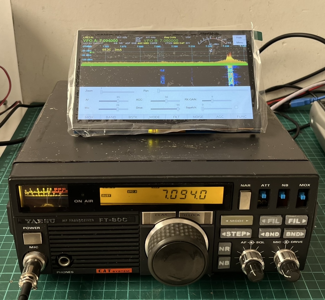
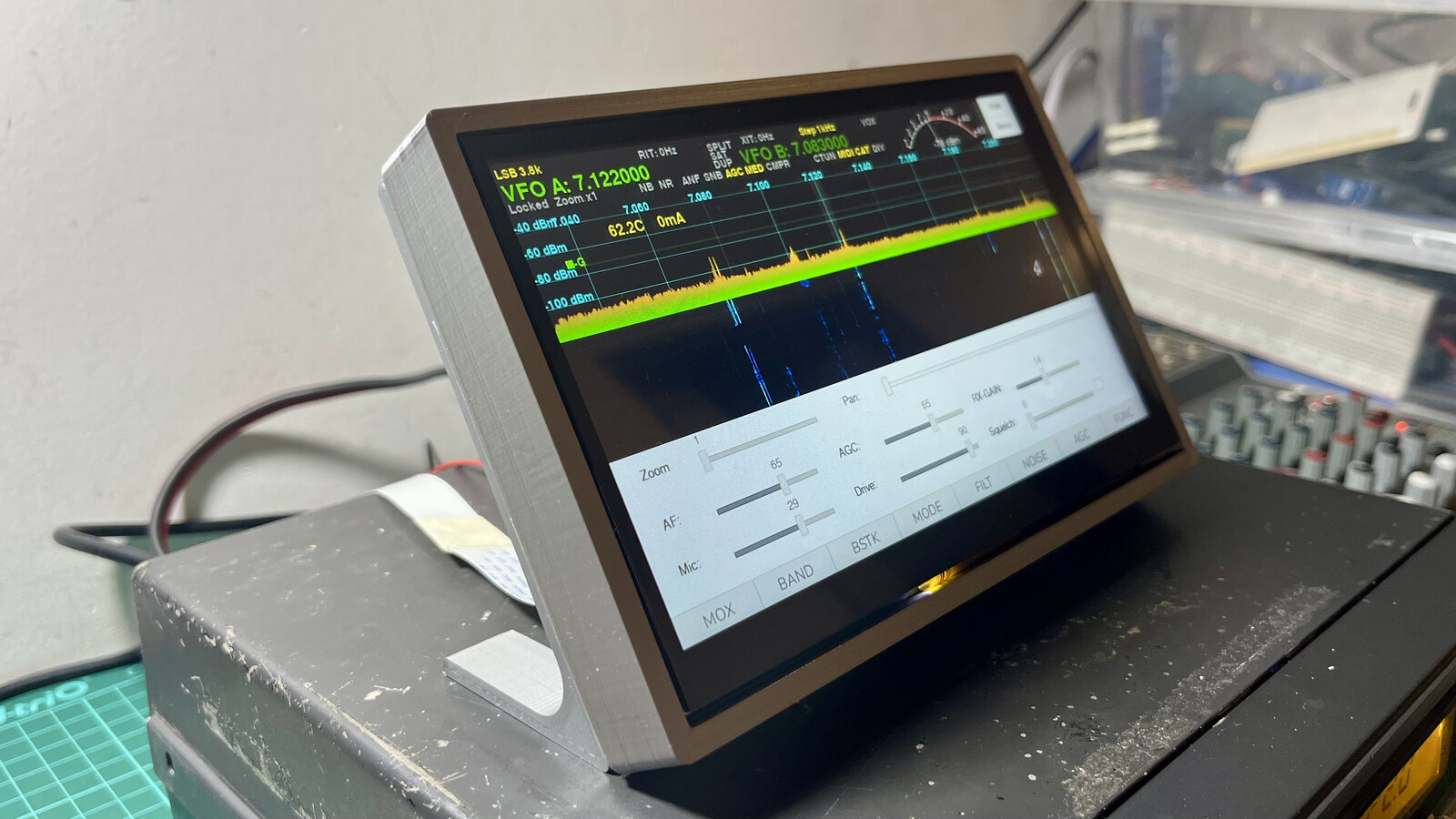
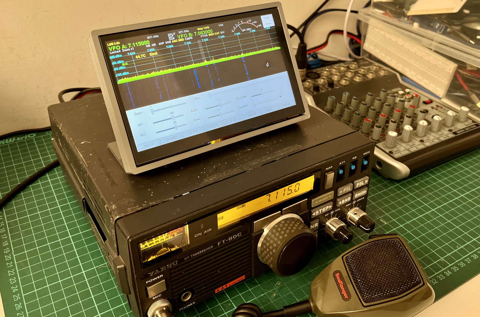
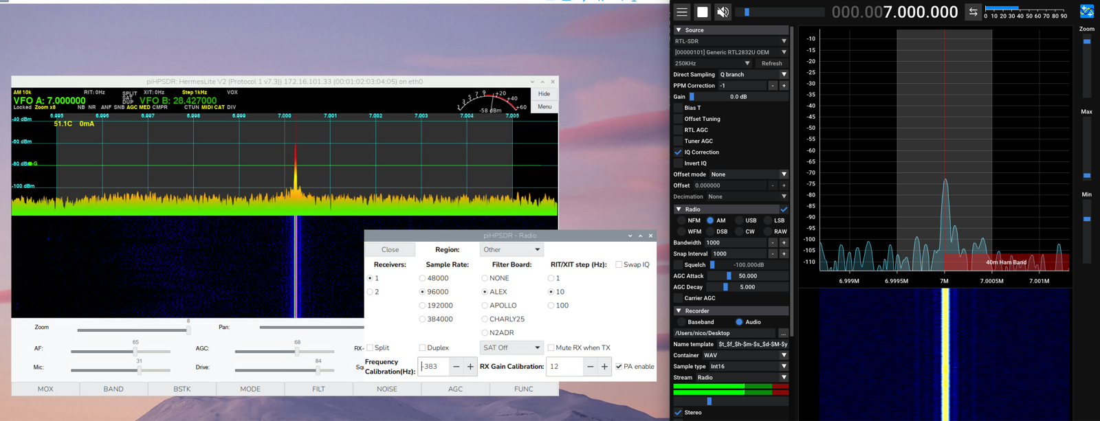
<?xml version="1.0" encoding="utf-8"?><feed xmlns="http://www.w3.org/2005/Atom" ><generator uri="https://jekyllrb.com/" version="4.4.1">Jekyll</generator><link href="https://blog.nico.ninja/feed.xml" rel="self" type="application/atom+xml" /><link href="https://blog.nico.ninja/" rel="alternate" type="text/html" /><updated>2026-09-16T03:36:54+00:00</updated><id>https://blog.nico.ninja/feed.xml</id><title type="html">nico.ninja</title><subtitle>Electronics, computers, radio, IoT, motorsports, software development and microcontroller-based projects</subtitle><author><name>Nicolas Rey</name></author><entry><title type="html">Building a SatNOGS ground station</title><link href="https://blog.nico.ninja/my-satnogs-station/" rel="alternate" type="text/html" title="Building a SatNOGS ground station" /><published>2026-08-08T21:20:00+00:00</published><updated>2026-08-08T21:20:00+00:00</updated><id>https://blog.nico.ninja/my-satnogs-station</id><content type="html" xml:base="https://blog.nico.ninja/my-satnogs-station/"><![CDATA[<p>My VHF OpenWebRX+ receiver was working flawlessly for months, and in the last few weeks I’ve been thinking of building something similar for the UHF band, given that there is a lot of satellite activity nowadays.</p>
<ul>
  <li><a href="#the-turnstile-antenna">The turnstile antenna</a></li>
  <li><a href="#adding-an-lna-and-the-cavity-filter-v1">Adding an LNA and the cavity filter V1</a></li>
  <li><a href="#replacing-the-antenna">Replacing the antenna</a></li>
  <li><a href="#cavity-filter-v2">Cavity filter V2</a></li>
  <li><a href="#conclusion">Conclusion</a></li>
</ul>

<h1 id="the-turnstile-antenna">The turnstile antenna</h1>

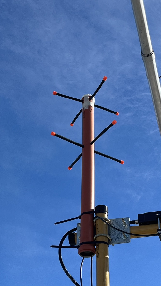
<p>At first I thought of adding a second SDR receiver to the OpenWebRX+ instance. Still, later I realized that I could convert a second SDR into a satNOGS station! Since I had some spare LMR-400 cable and PVC tubing, I built a double-turnstile antenna and hooked it up to the RTL-SDR v3 receiver.</p>

<p><img src="../assets/images/satnogs-station-1/turnstile-antenna-mounted.jpeg" alt="Turnstile antenna v1" /></p>

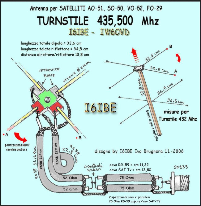
<p>I have used the instructions from I6IBE to build the antenna, taking care of the phasing stubs; nevertheless, I haven’t found any good resonance points anywhere near 436 MHz. Here are the instructions if someone else is interested in building it:</p>

<p><img src="../assets/images/satnogs-station-1/i6ibe-turnstile-diagram.jpg" alt="I6IBE turnstile building diagram" /></p>

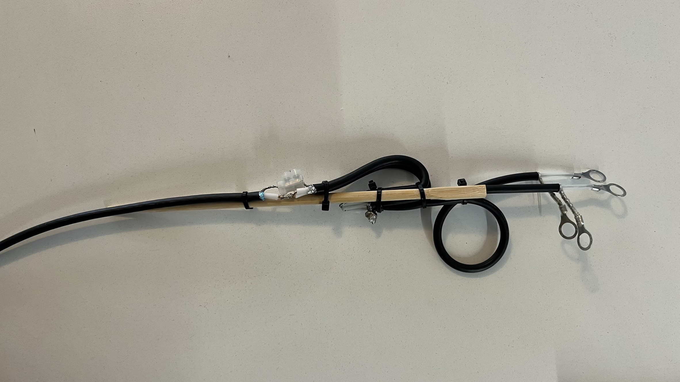
<p>I haven’t found a way to tune up the VSWR correctly; after some investigation, I learned that the best way is to tune up either the two parallel 75-ohm stubs or the two 52-ohm phasing coaxes. The stub design was also correlated with <a href="https://www.radioamatoripeligni.it/i6ibe/turnhard/turnhard.htm">these instructions I found</a>.</p>

<p><img src="../assets/images/satnogs-station-1/turnstile-stubs-1.jpeg" alt="Stubs for the turnstile antenna" /></p>

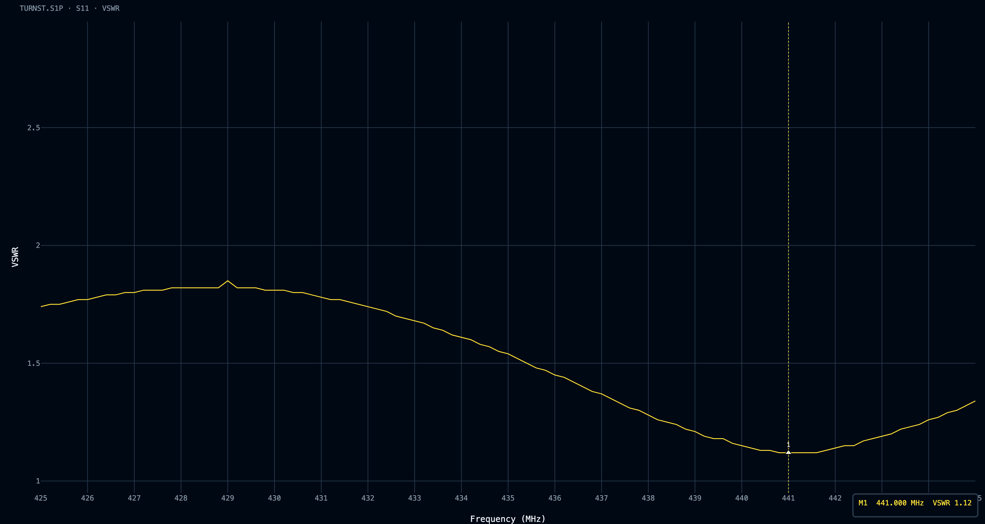
<p>I built a few versions varying lengths and trying other 75-ohm coaxes like RG-6 and RG-59, but none gave me a great VSWR result or a great resonance point at ~436 MHz. I made sure to use the correct VF for each cable; nevertheless, I haven’t had any luck tuning them correctly.</p>

<p><a href="../assets/images/satnogs-station-1/TURNST_vswr_20260805.png" target="_blank"><img src="../assets/images/satnogs-station-1/TURNST_vswr_20260805.png" alt="Turnstile VSWR curve" /></a></p>

<p>I built a few versions varying lengths and trying other 75-ohm coaxes like RG-6 and RG-59, but none gave me a great VSWR result or a great resonance point at ~436 MHz. I made sure to use the correct VF for each cable; nevertheless, I haven’t had any luck tuning them correctly.</p>

<h1 id="adding-an-lna-and-the-cavity-filter-v1">Adding an LNA and the cavity filter V1</h1>

<p>I thought, what if I set up an SPF5189z LNA in front of the RTL-SDR receiver? My first thought was that it might overload due to the high amplification bandwidth of that LNA, and I would need to build a bandpass filter for ~436 MHz.</p>

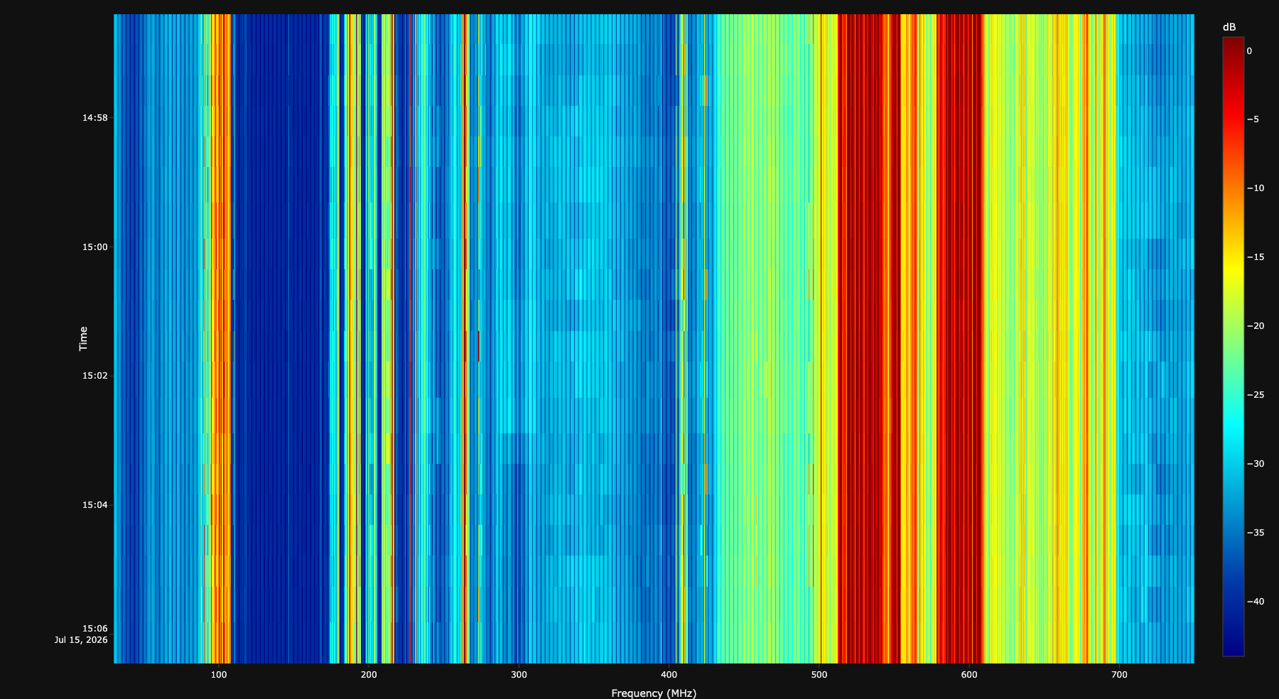
<p>I ran a <a href="../assets/files/satnogs-station-1/waterfall.py">small Python script</a> to parse the data generated from rtl_power. I swept from 30 to 750 MHz, as I was mainly interested in how the ISDB-T signals around 520 to 600 MHz may affect the reception.</p>

<pre><code class="language-bash">rtl_power -f 30M:750M:25k -g 30 -T -i 30 -e 10m gain30-10min-30-750mhz-step25khz.csv
</code></pre>

<p><a href="../assets/files/satnogs-station-1/waterfall.py">The script</a> brings up a web server to analyze the CSV files in the same folder so one can compare waterfalls with just two browser tabs open, as well as export the generated graphs</p>

<p><a href="../assets/images/satnogs-station-1/plot-30-750MHz-gain20-no-filter.png" target="_blank"><img src="../assets/images/satnogs-station-1/plot-30-750MHz-gain20-no-filter.png" alt="rtl_power plot from 30 to 750 MHz without filter" /></a></p>
<blockquote>
  <p><a href="../assets/files/satnogs-station-1/gain20-10min-30-750mhz-step25khz-direct.csv">Download the .csv file</a></p>
</blockquote>

<p>And indeed, the ISDB-T strong signals were there, overloading almost from 400 to 700 MHz, so I put my hands on building a filter. I don’t have any experience with filters, so I learned a lot with this. I actually went <em>too</em> deep at some point, and it took me almost two months of experimentation.</p>

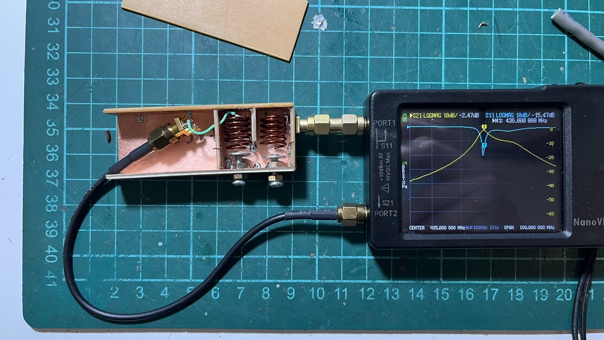
<p>It’s been a while since I was wondering how a cavity filter would perform. Since I have never built one, and since the wavelength of the UHF band is fairly short, I put my hands to work and built one. Let’s call this one the cavity filter V1.</p>

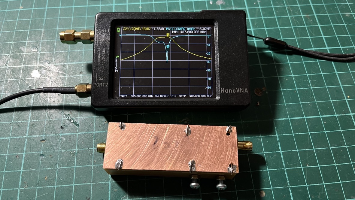
<p><img src="../assets/images/satnogs-station-1/cavity-filter-v1-measurement.jpeg" alt="Cavity filter V1 measurements" /></p>

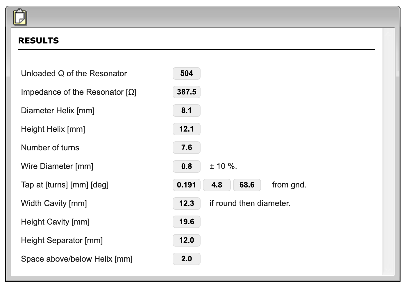
<p>I didn’t have spare double-sided PCB pieces, so I used Pertinax single-sided PCBs. While not ideal, they’re acceptable for a first filter. For the calculations, I used the <a href="https://www.changpuak.ch/electronics/Helical_Bandpass_Filter_Designer.php">Changpuak’s Helical Bandpass filter designer</a>.</p>

<p><a href="../assets/images/satnogs-station-1/changpuak-calculator-results.png" target="_blank"><img src="../assets/images/satnogs-station-1/changpuak-calculator-results.png" alt="Changpuak's helical bpf calcs" /></a></p>

<p>The center frequency I set was 435 MHz with a bandwidth of 10 MHz. The calculations gave me:</p>

<ul>
  <li>Helix diameter: 8.1 mm</li>
  <li>Helix length: 12.1 mm</li>
  <li>Number of turns: 7.6</li>
  <li>Wire gauge: 0.8 mm</li>
  <li>Cavity Width x Height: 12.3 x 19.6 mm</li>
  <li>Separator height: 12 mm</li>
</ul>

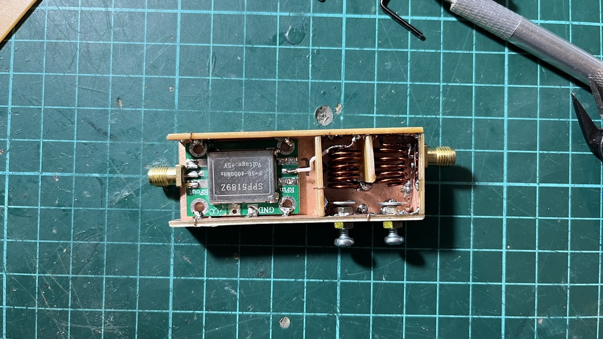
<p><img src="../assets/images/satnogs-station-1/lna-and-cavity-filter-v1.jpeg" alt="LNA and cavity filter v1" /></p>

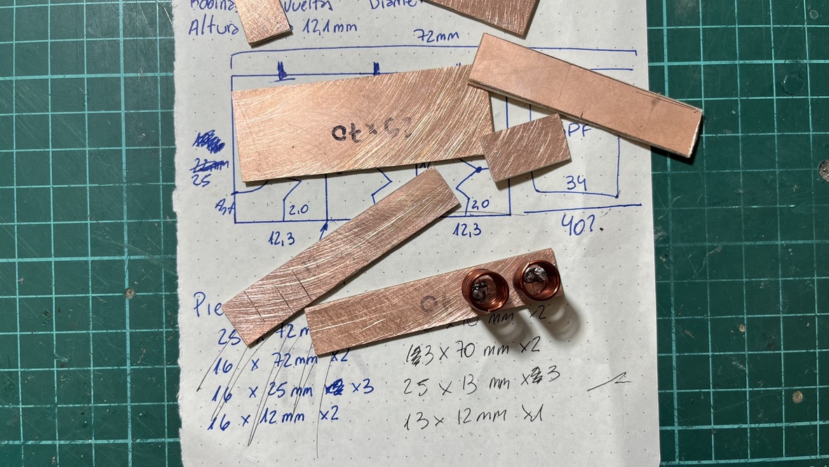
<p>I only had 1.02 mm (AWG 18) enamel wire so that the coil would be a bit sturdy. I chose an 8 mm drill to wind the coil and used <a href="https://www.cutlistoptimizer.com/">https://www.cutlistoptimizer.com/</a> to see how to cut the PCB to get all the pieces. I made the pieces a bit longer so I could install the LNA inside the same filter assembly.</p>

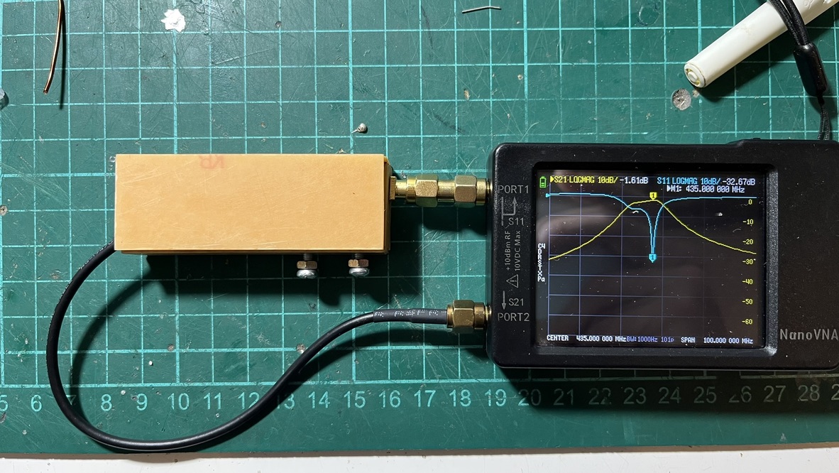
<p><img src="../assets/images/satnogs-station-1/lna-and-cavity-filter-v1-vna.jpeg" alt="VNA measurements for cavity filter v1" /></p>

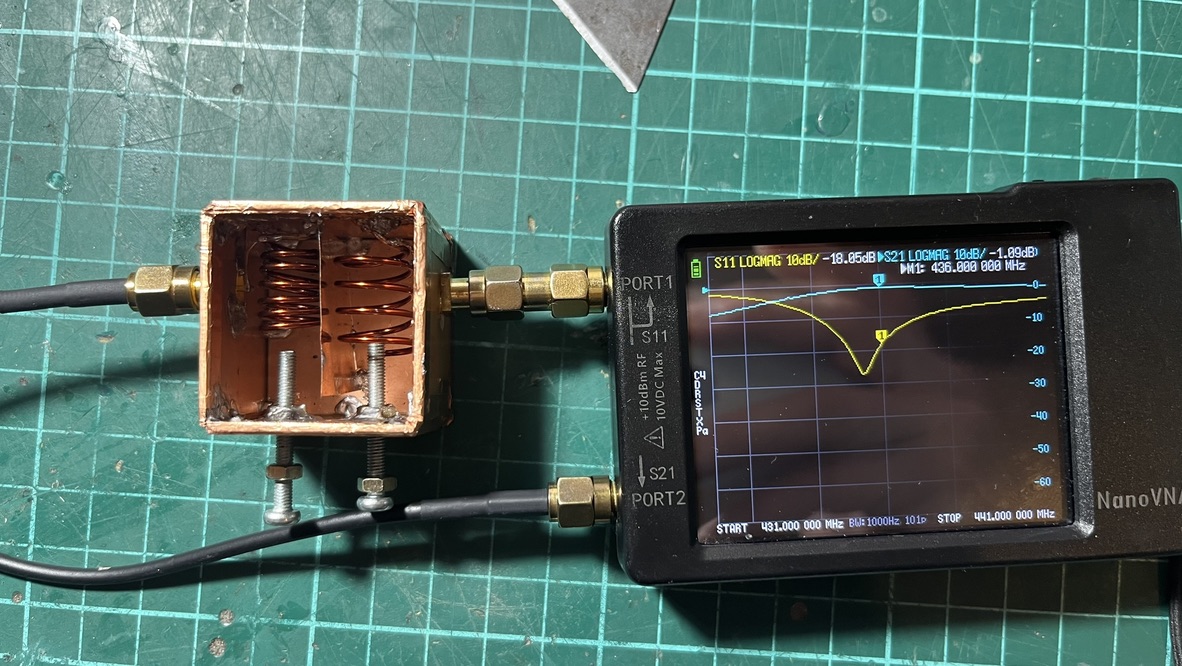
<p>TL;DR: Each cavity measured 12.5 mm wide, 22 mm long, and 13 mm tall. I had to tune the coils a bit; one ended with 6 1/2 turns, and the other with 5 1/2 turns. I used two M3 x 10 mm screws and soldered M3 x 9 mm washers to the ends of the screws for tuning. The taps (in and out) were set in around 0.25 to 0.3 turns each. During my experiments, I noted that the tap position is one of the most important things to tune out. If the tap is misplaced, reflection (S11) ends up too high.</p>

<p><img src="../assets/images/satnogs-station-1/cavity-filter-v1-pieces.jpeg" alt="Cavity filter v1 pieces" /></p>

<p>First, I cut all the pieces with a knife, then sanded them to fit together. The PCB thickness is relevant; it adds (in my case) 1.6 mm to each measurement, which is not negligible, so you may want to take that into account when calculating the cuts.</p>

<p>Then mounted the two coils, soldering them to the 70 x 13 mm board, spaced 12.5 mm apart. Each coil is mounted in the center of each cavity, with very small room for the coupling window. The coupling window (or separator) is about 12 x 13 mm. I tried creating a larger window (by cutting a smaller separator of 10 x 13 mm), but the filter suffered from over-coupling (S21 showed two humps with a sag in the middle). Nevertheless, I think the filter ended up under-coupled, since the S11 return loss was not good outside the 5 MHz bandpass, and we expected the filter to be 10 MHz wide</p>

<p><img src="../assets/images/satnogs-station-1/cavity-filter-v1-measurements.jpeg" alt="VNA measurements for cavity filter v1" /></p>

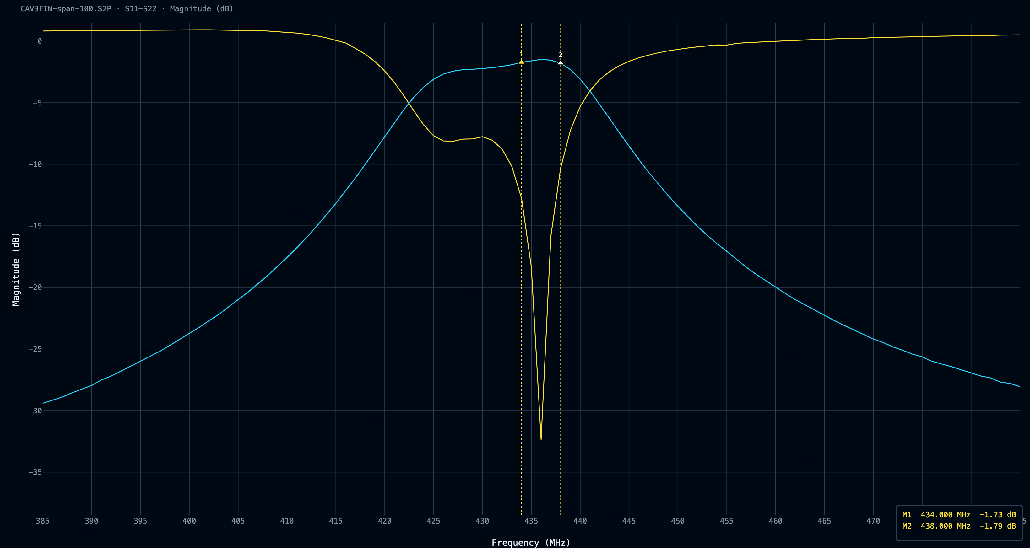
<p>While the filter did get, let’s say, “ok” S21 attenuation of around -1.7 dB across our interest frequency window, the S11 reflection levels were a bit mediocre. I was expecting −15 dB or better return loss, hence a low VSWR across the passband. A quick note on terminology, because I mixed these up myself for weeks: S11 is return loss (how much power bounces back at the input), passband S21 is insertion loss (how much the signal is attenuated going through). Stopband S21 is rejection (how well the filter kills what you don’t want).</p>

<p><a href="../assets/images/satnogs-station-1/CAV3FIN-span-100_db_20260805.png" target="_blank"><img src="../assets/images/satnogs-station-1/CAV3FIN-span-100_db_20260805.png" alt="Cavity filter v1 final traces" /></a></p>
<blockquote>
  <p><a href="../assets/files/satnogs-station-1/cavity-v1-433-span-100.S2P">Download the .s2p file</a></p>
</blockquote>

<p>I made a few tweaks to the coils; at first, they were wound over an 8 mm-diameter drill, which was too much. There was little to no space between the coils and the walls, and they touched constantly, losing resonance. I rewound the coils in a 7 mm drill, and that was way better.</p>

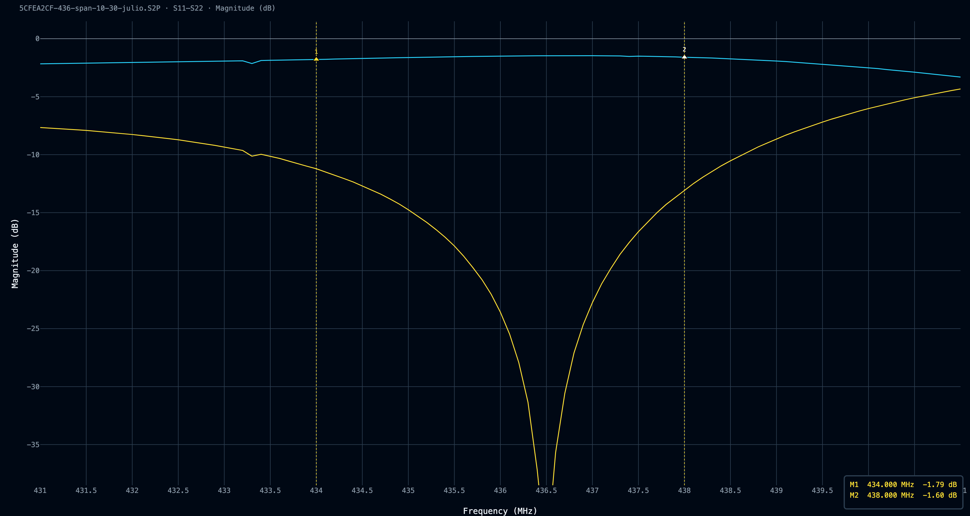
<p>I spent over 3 hours tuning the filter; I cannot tell you how sensitive it is to almost everything. Moved the separator 0.5 mm? You lost 4 dB in S21. Is the filter case not fully closed? The resonant frequency is now 3 MHz higher. The best I could get was around -1.47 dB of insertion loss with -12 dB of S11 rejection, but with a very strange S11 curve, where it seems one of the cavities is lost (hence, just one dip), so I decided to hook it up to the turnstile antenna and the LNA, even though I had concerns at multiple levels.</p>

<p><a href="../assets/images/satnogs-station-1/5CFEA2CF-436-span-10-30-julio_db_20260805.png" target="_blank"><img src="../assets/images/satnogs-station-1/5CFEA2CF-436-span-10-30-julio_db_20260805.png" alt="Cavity filter v1 final traces zoomed" /></a></p>
<blockquote>
  <p><a href="../assets/files/satnogs-station-1/cavity-v1-436-span-10.S2P">Download the .s2p file</a></p>
</blockquote>

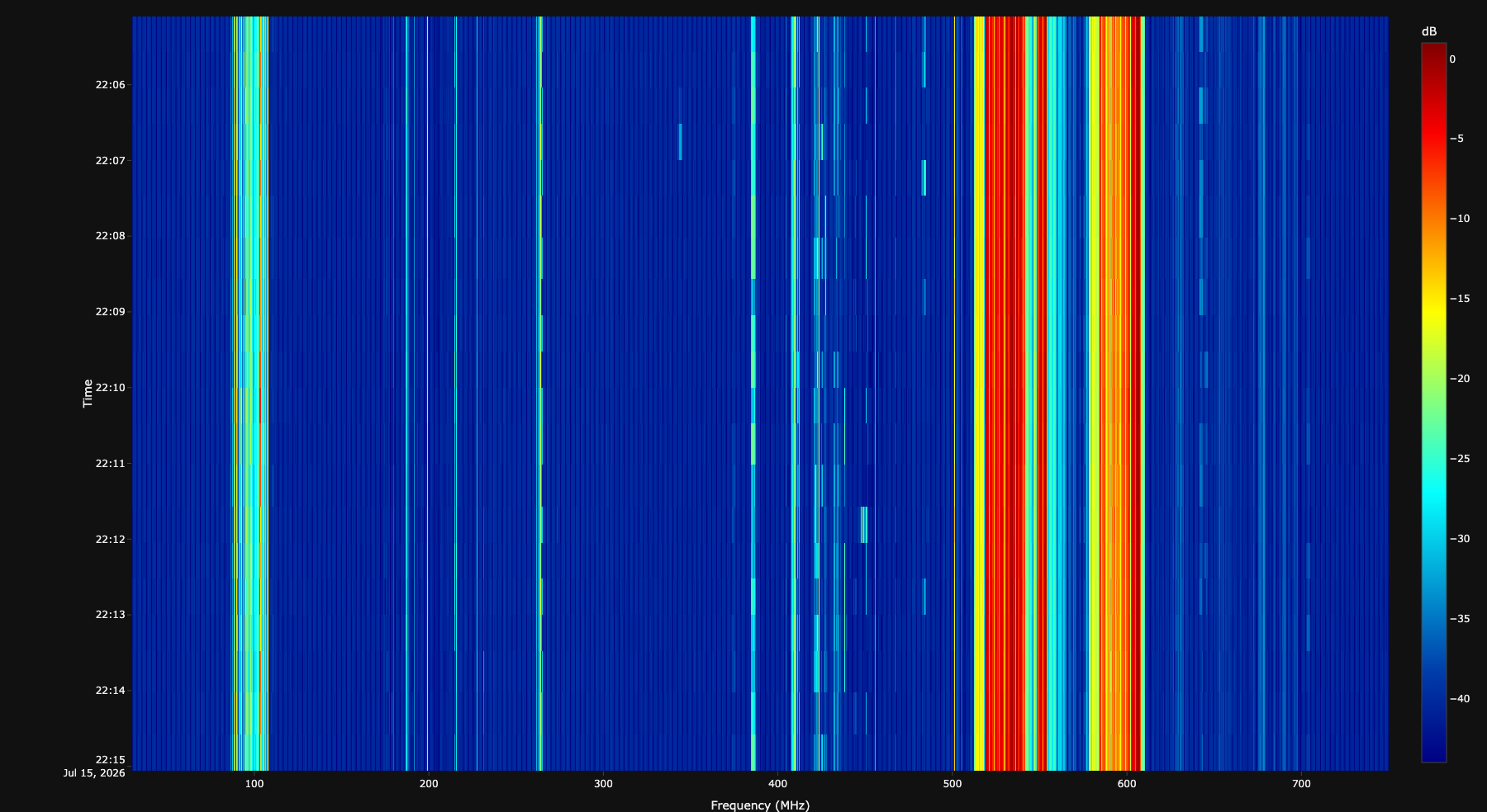
<p>After mounting the cavity filter, I re-ran the <code>rtl_power</code> script to check how things were looking now</p>

<p><a href="../assets/images/satnogs-station-1/plot-30-750MHz-gain20-cavity-filter.png" target="_blank"><img src="../assets/images/satnogs-station-1/plot-30-750MHz-gain20-cavity-filter.png" alt="rtl_power plot from 30 to 750 MHz with filter" /></a></p>
<blockquote>
  <p><a href="../assets/files/satnogs-station-1/gain20-10min-30-750mhz-step25khz-cavity.csv">Download the .csv file</a></p>
</blockquote>

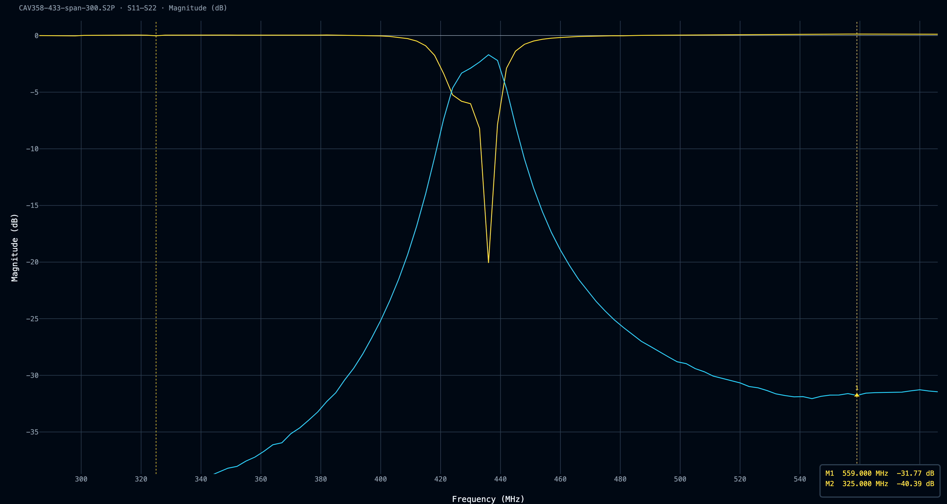
<p>That was much better! While the strong ISDB-T signals were still there, now they weren’t leaking RF power 300 MHz wide; also, the broadcast commercial FM stations were looking tidier, and the sub-FM noise was gone as well. Despite the filter doing filter things, when I swept the VNA with a 300 MHz span, I noticed that the bell curve didn’t go lower than -40dB. While I understand the Nano VNA has limited dynamic range, I expected a bell curve shape.</p>

<p><a href="../assets/images/satnogs-station-1/CAV358-433-span-300_db_20260805.png" target="_blank"><img src="../assets/images/satnogs-station-1/CAV358-433-span-300_db_20260805.png" alt="Cavity filter v1 final traces 300MHz span" /></a></p>
<blockquote>
  <p><a href="../assets/files/satnogs-station-1/cavity-v1-433-span-300.S2P">Download the .s2p file</a></p>
</blockquote>

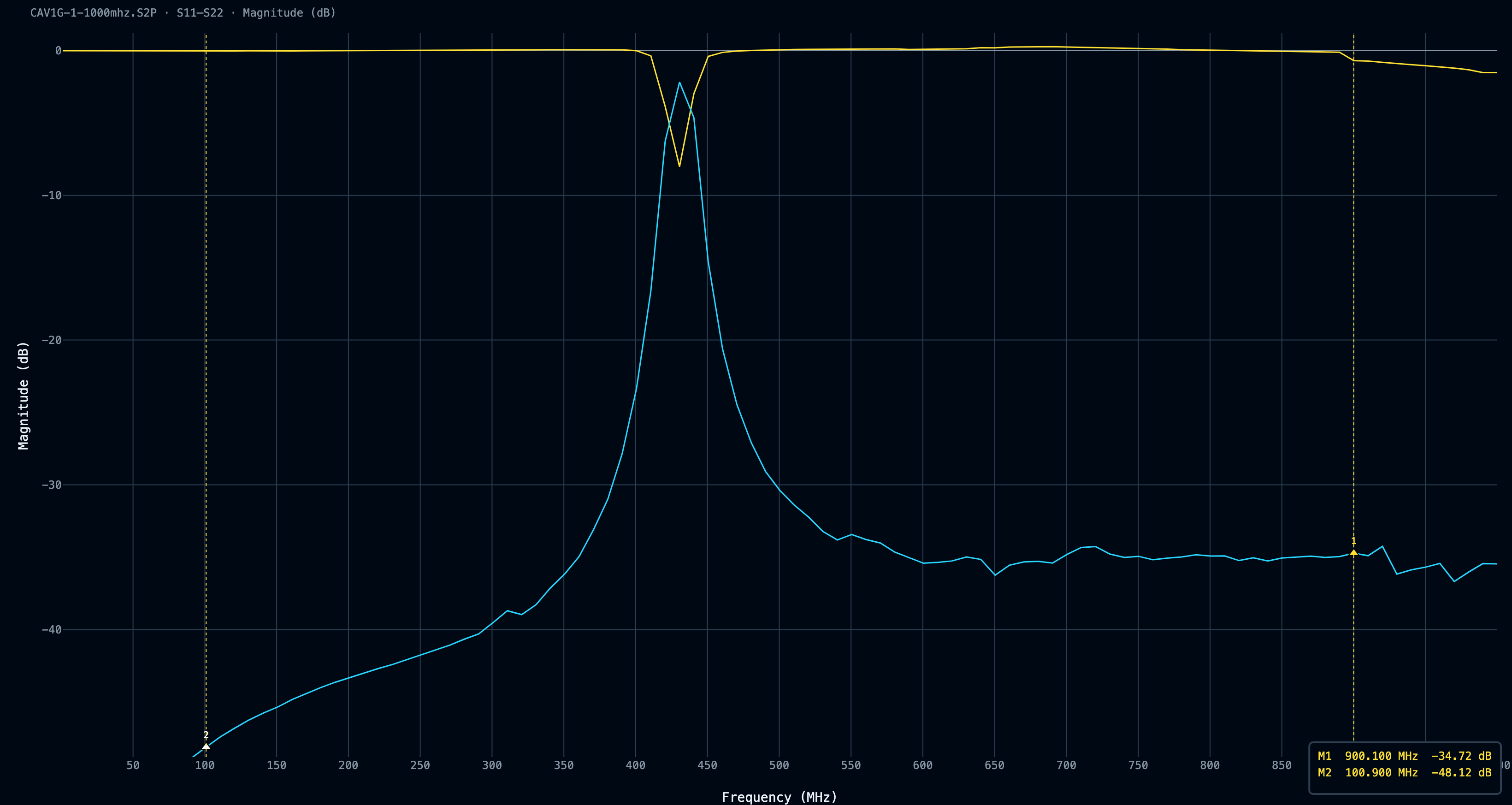
<p>I did a last sweep from 1 MHz to 1 GHz, taking into account the Nano VNA’s limited resolution, of course, but concentrating more on the shape than on the power levels; the flatness on the high side of the filter stayed at ~ -40 dB. Here I started to hypothesize an RF leakage in the filter. A flat line usually means you are looking at leakage around the filter, through the gaps in the box, or through the VNA and the fixture itself. However, I was very tired, so I called it a day and moved on.</p>

<p><a href="../assets/images/satnogs-station-1/CAV1G-1-1000mhz_db_20260805.png" target="_blank"><img src="../assets/images/satnogs-station-1/CAV1G-1-1000mhz_db_20260805.png" alt="Cavity filter v1 final traces 1GHz span" /></a></p>
<blockquote>
  <p><a href="../assets/files/satnogs-station-1/cavity-v1-1-1000mhz.S2P">Download the .s2p file</a></p>
</blockquote>

<h1 id="replacing-the-antenna">Replacing the antenna</h1>

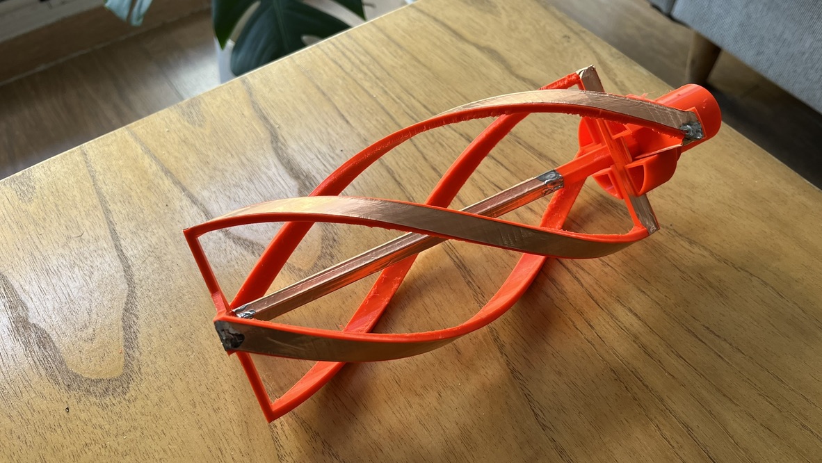
<p>During my investigation, I found a pretty neat QFH antenna design made of 3D-printed parts by <a href="https://sa0pej.wordpress.com/3d-print-and-build-qfa-antenna/">SA0PEJ</a>, so I put my hands on it. Jan, SA0PEJ, did an incredible journey through quadrifilar helicoidal antennas, which is <a href="https://sa0pej.wordpress.com/qfa-antenna/">well worth reading</a>.</p>

<p>Printing was over 12 or 13 hours. I made it without supports. I could have improved printing quality with supports, but this is a test version, and I don’t care much about surface quality.</p>

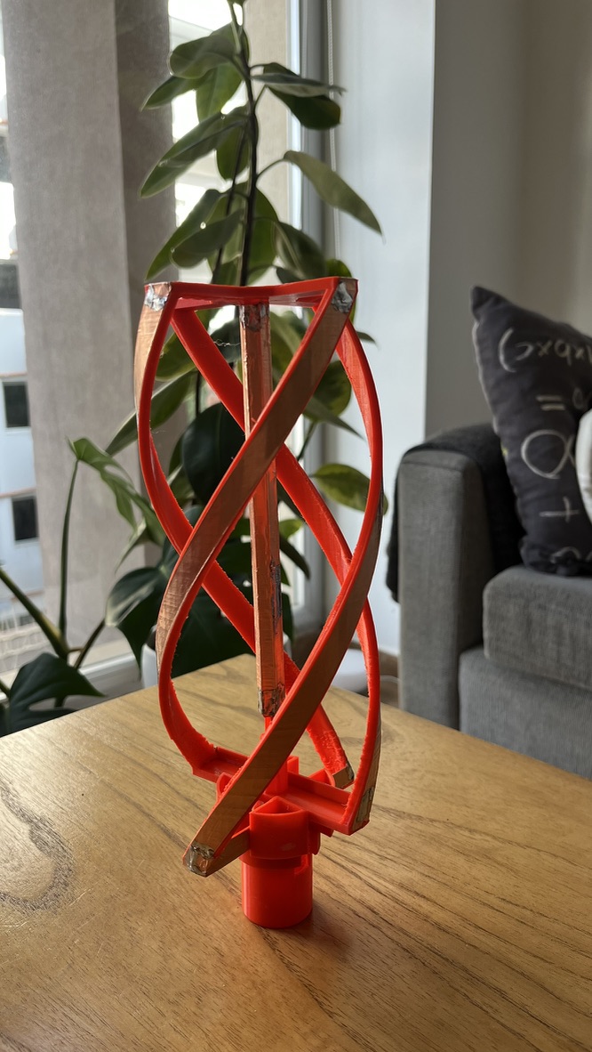
<p><img src="../assets/images/satnogs-station-1/qfh-over-table-1.jpeg" alt="QFH over table" /></p>

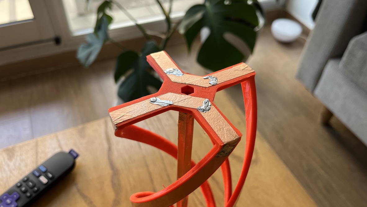
<p>I bought a roll of copper tape, 10 mm wide, to make the elements. It is incredible how easy it is to solder this thing.</p>

<p><img src="../assets/images/satnogs-station-1/qfh-feed-solder.jpeg" alt="QFH feed detail" /></p>

<p>The feed line is drawn from the center of the antenna, and the antenna is fed from the top. A sleeve or bazooka balun is built with the same copper tape, by masking the central tube, taking care to maintain lambda/4 lengths, or 175 mm for this antenna.</p>

<p><img src="../assets/images/satnogs-station-1/qfh-elements.jpeg" alt="QFH elements" /></p>

<p>I printed this first version in PLA because it’s what I had spare. Two separate things push the resonance around here: the printed geometry itself (scale and shrinkage move the element lengths) and dielectric loading (the plastic sitting against the conductors has a permittivity above air, which lowers the resonant frequency for the same physical size). Mine ended up slightly large and resonating a bit low. For a receive-only station, I don’t think it’s a big deal.</p>

<p>If you build one, use PETG. PLA’s glass transition is around 60 °C, and a plastic antenna in direct summer sun will soften and sag; on a QFH, the element geometry <em>is</em> the phasing, so a sagging former is a detuned antenna. This one is a test version, and I’ll mine with that; the permanent one gets reprinted in PETG.</p>

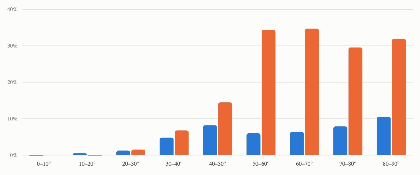
<p>The QFH was mounted using the same feed line, the same cavity filter V1, and the same LNA I was already using. I just tuned the gain a bit. That’s deliberate: the only variable that changed between these two datasets is the antenna itself; everything downstream stayed identical, and both ran for weeks over many passes. I left it working until I had enough comparison data between both antennas, and I got… Amazed.”</p>

<p><a href="../assets/images/satnogs-station-1/antenna-comparison.png" target="_blank"><img src="../assets/images/satnogs-station-1/antenna-comparison.png" alt="Turnstile and QFH antenna comparison" /></a></p>

<p>I don’t think the turnstile is a bad antenna at all. The thing is that I couldn’t build one accurately enough.</p>

<p>The obvious suspect with a coaxial phasing harness is velocity factor. Solid-PE RG-59 runs around 0.66 and foam RG-6 around 0.85, so cutting both to the same physical length gives you two very different electrical lengths. I did the math separately for each cable and cut each one accordingly; nevertheless, that didn’t fix the antenna resonance point.</p>

<p>What’s left is harder to see with the measurement I was taking. S11 through the assembled harness gives you a single number for the whole thing. Hence, an asymmetry between the two dipoles, a phase error in the T junction, and wrong reflector spacing all look identical from the connector. Without properly choking the VNA lead, you are also partly measuring common-mode current on the feedline instead of the antenna. The right way to debug it is to characterize each dipole and each harness section individually, before assembly.</p>

<h1 id="cavity-filter-v2">Cavity filter V2</h1>

<p>Back when I built the first cavity filter, I ended with results that were not so good. So I started to play a bit with what I will refer to as the cavity filter v2. Things I changed:</p>

<ol>
  <li>Cavity sizing: I deliberately decided to build bigger cavities to accommodate bigger (more diameter) coils.</li>
  <li>Wind bigger-diameter coils: my rationale here was to increase the overall Qu of the filter (due to a combination of bigger cavities and bigger coils), while maintaining a coil diameter (d) over a shield size (S) ratio <code>d/S = 0.66</code>. The goal is to improve the passband loss.</li>
  <li>Thinner coupling wall: Instead of using a piece of PCB for the separator, I used a 0.05 mm copper sheet to separate each cavity from the others, gaining ~ 1.5 mm between them.</li>
  <li>Get rid of the washers: Instead, use longer M3 screws for more precise adjustment. During my testing with the cavity filter V1, I felt like the screw tuning was VERY sensitive, in part because of the nature of the filter, but also due to the 9 mm washers in front of the coils.</li>
  <li>Build the filter as a whole object: remove the LNA from the board so it is easier to do new measurements.</li>
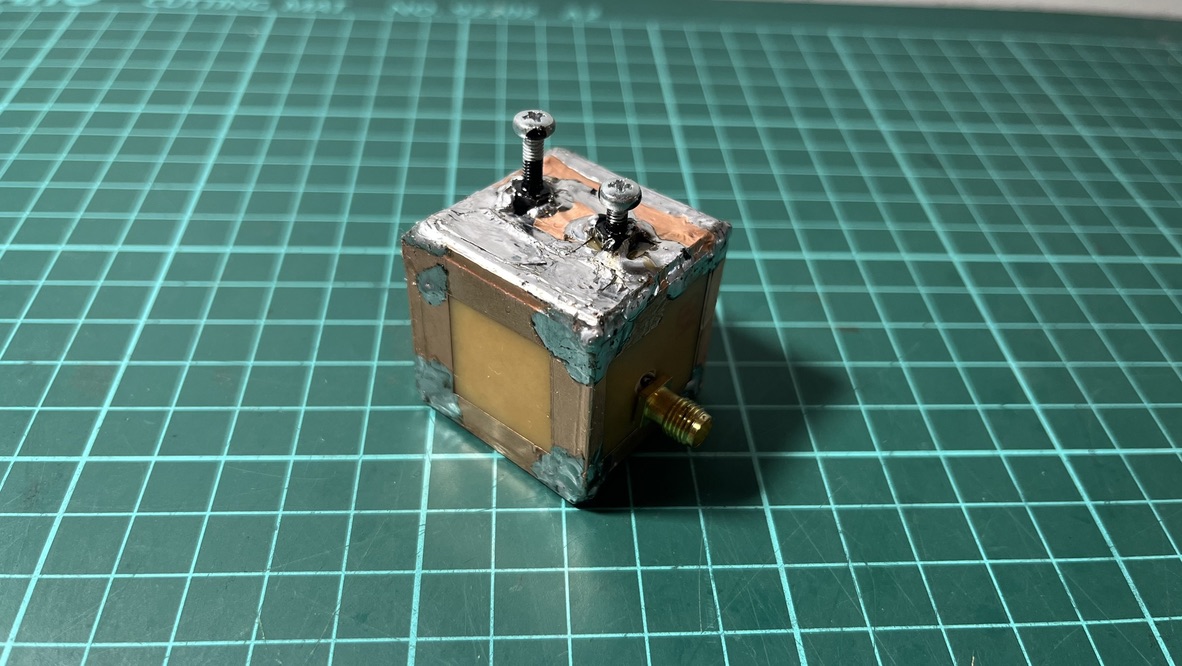
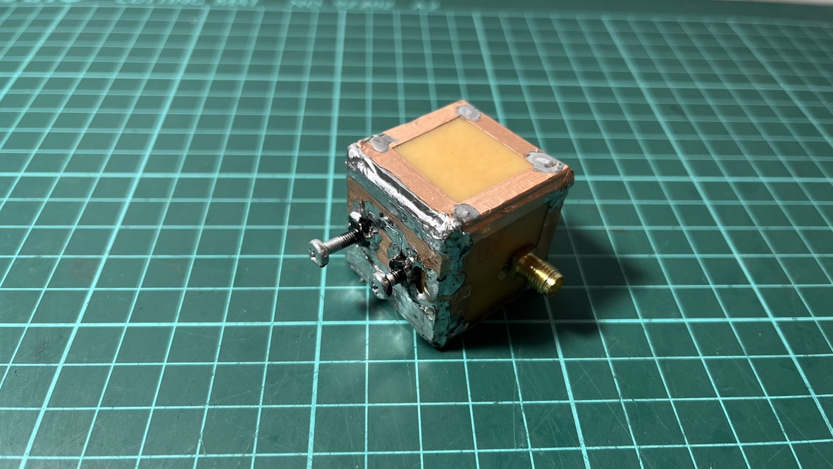
  <li>Use lots of copper tape to shield the filter box: in the V1 design, there were a lot of open gaps here and there in the box, most likely leading to RF leakage.</li>
</ol>

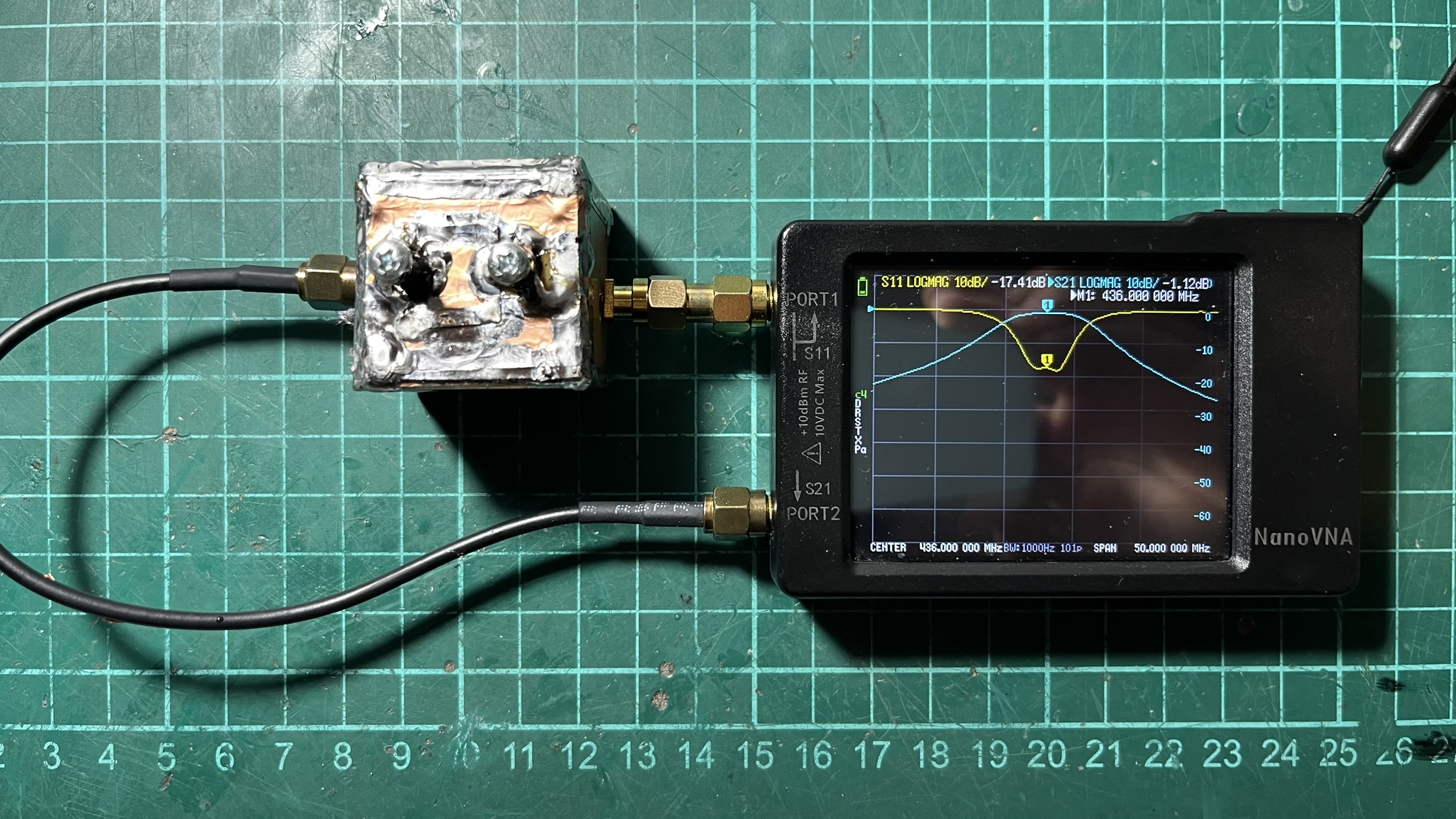
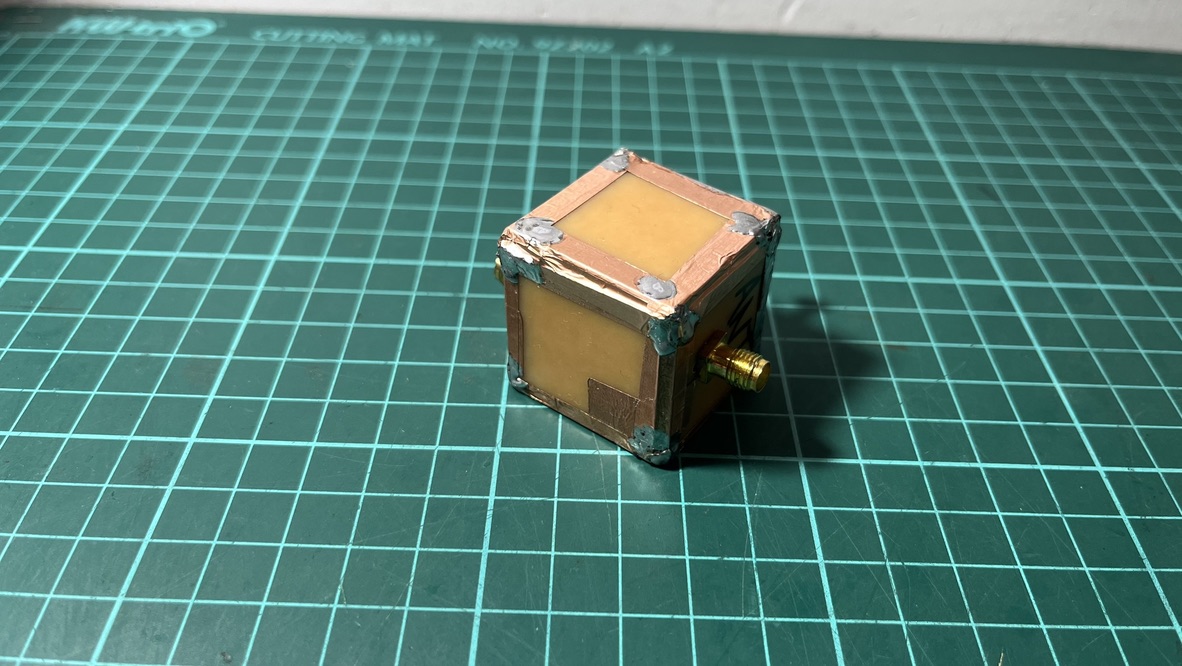
<p><img src="../assets/images/satnogs-station-1/cavity-filter-v2-initial.jpeg" alt="Cavity filter v2" /></p>

<p>Each cavity of the cavity filter V2 measures 15 mm wide x 30 mm tall x 30 mm long. The coils were made with the same AWG 18 (1.02 mm) copper enamel wire, but this time wound over a 10 mm drill, 4.5 turns. The separator wall is 22 mm long, and the new bolts are M3 x 25 mm long.</p>

<p><img src="../assets/images/satnogs-station-1/cavity-filter-v2-50mhz-span.jpeg" alt="Cavity filter v2 at 50MHz span" /></p>

<p><img src="../assets/images/satnogs-station-1/cavity-filter-v2-bottom.jpeg" alt="Cavity filter v2 bottom" /></p>

<p><img src="../assets/images/satnogs-station-1/cavity-filter-v2-top.jpeg" alt="Cavity filter v2 top" /></p>

<p><img src="../assets/images/satnogs-station-1/cavity-filter-v2-back.jpeg" alt="Cavity filter v2 back" /></p>

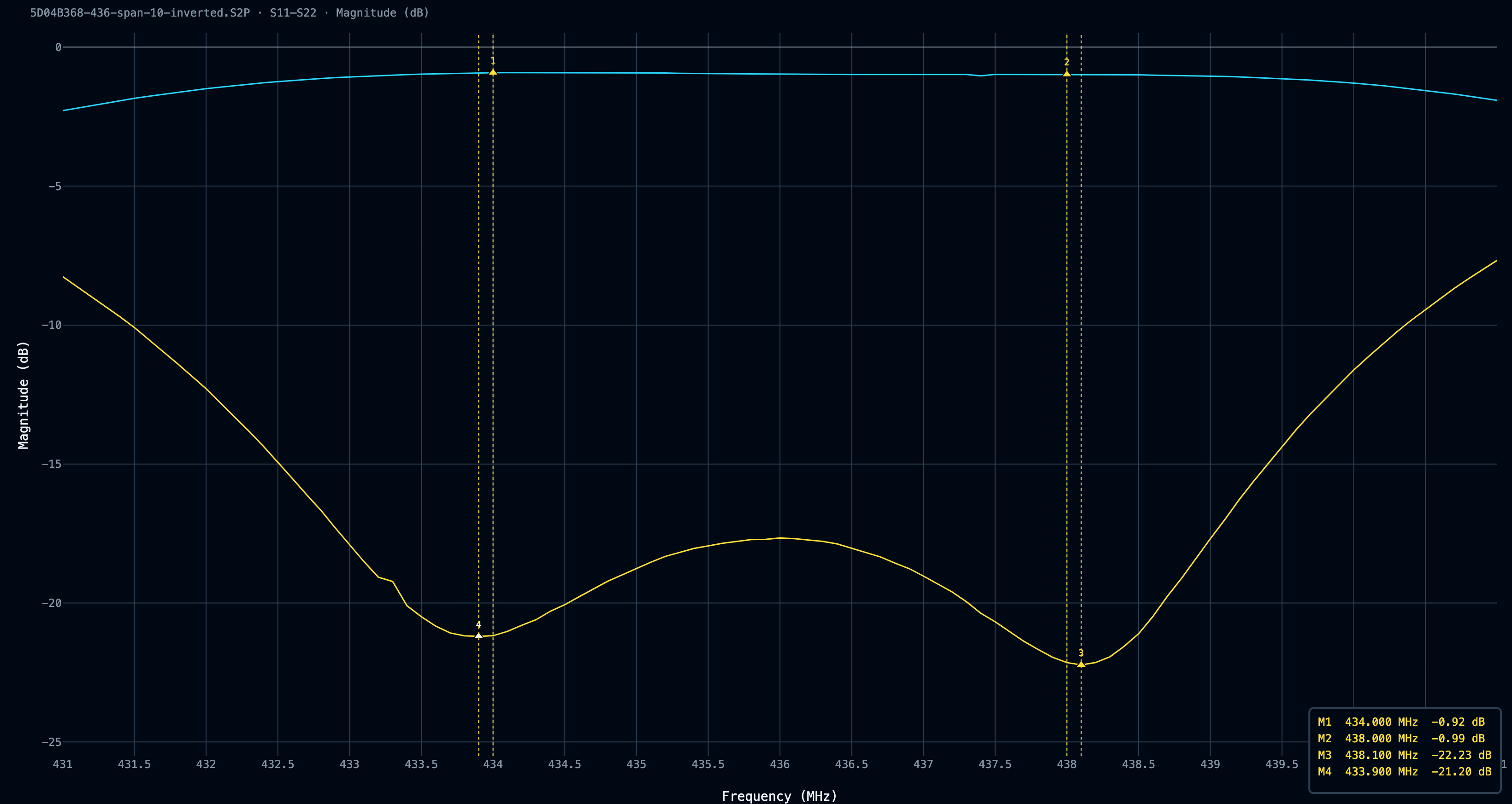
<p>After some fine tweaking of bolts and coil geometry (I ended up stretching the coils to make them longer), the filter behaved very well, at least on the bench. Worst-case insertion loss measured −0.99 dB at the passband edges, and worst-case return loss was −17.65 dB at 436 MHz. My reading on the improvements is:</p>

<p><strong>Bigger cavities bought margin:</strong> Roughly doubling the cavity size roughly doubles the theoretical unloaded Q, which on paper is worth something like 0.4 dB of insertion loss.</p>

<p><strong>Bigger cavities also bought tolerance:</strong> In V1, the tap was a few millimeters of 1 mm wire, in a position where a couple of tenths of a millimeter materially changes the match; the solder joint itself perturbs the thing you are trying to set. V1’s S11 dB return loss is the signature of an undercoupled tap, and I had no way to move it in that little box. At 15 mm, the tap becomes an easy task, and most of the return loss improvement came from finally being able to place it properly.</p>

<p><a href="../assets/images/satnogs-station-1/5D04B368-436-span-10-inverted_db_20260806.png" target="_blank"><img src="../assets/images/satnogs-station-1/5D04B368-436-span-10-inverted_db_20260806.png" alt="Cavity filter v2 span 10MHz" /></a></p>
<blockquote>
  <p><a href="../assets/files/satnogs-station-1/cavity-v2-436-span-10.S2P">Download the .s2p file</a></p>
</blockquote>

<p>Something I hadn’t taken into account before was the importance of a good S11 rejection level; I was too focused on the S21 bandpass attenuation and completely forgot to aim for good S11 values.</p>

<table>
  <thead>
    <tr>
      <th>S11 (return loss)</th>
      <th>VSWR</th>
      <th>Power reflected</th>
      <th>Mismatch loss</th>
    </tr>
  </thead>
  <tbody>
    <tr>
      <td>−10 dB</td>
      <td>1.92</td>
      <td>10%</td>
      <td>0.458 dB</td>
    </tr>
    <tr>
      <td>−15 dB</td>
      <td>1.43</td>
      <td>3.2%</td>
      <td>0.140 dB</td>
    </tr>
    <tr>
      <td>−17.65 dB</td>
      <td>1.30</td>
      <td>1.7%</td>
      <td>0.076 dB</td>
    </tr>
    <tr>
      <td>−20 dB</td>
      <td>1.22</td>
      <td>1.0%</td>
      <td>0.044 dB</td>
    </tr>
    <tr>
      <td>−22 dB</td>
      <td>1.17</td>
      <td>0.6%</td>
      <td>0.028 dB</td>
    </tr>
    <tr>
      <td>−30 dB</td>
      <td>1.07</td>
      <td>0.1%</td>
      <td>0.004 dB</td>
    </tr>
  </tbody>
</table>

<p>That table shows how S11 affects the VSWR, thereby the mismatch loss (added to the S21 bandpass loss) added to the system. TL;DR: virtually any S11 reflection better than -15 dB is good enough for a filter.</p>

<p><a href="../assets/images/satnogs-station-1/compare_db_20260806.png" target="_blank"><img src="../assets/images/satnogs-station-1/compare_db_20260806.png" alt="Cavity filter v1 vs v2 1GHz span" /></a></p>
<blockquote>
  <p><a href="../assets/files/satnogs-station-1/cavity-v1-1-1000mhz.S2P">Cavity V1 .s2p file</a>, <a href="../assets/files/satnogs-station-1/cavity-v2-1-1000.S2P">Cavity V2 .s2p file</a></p>
</blockquote>

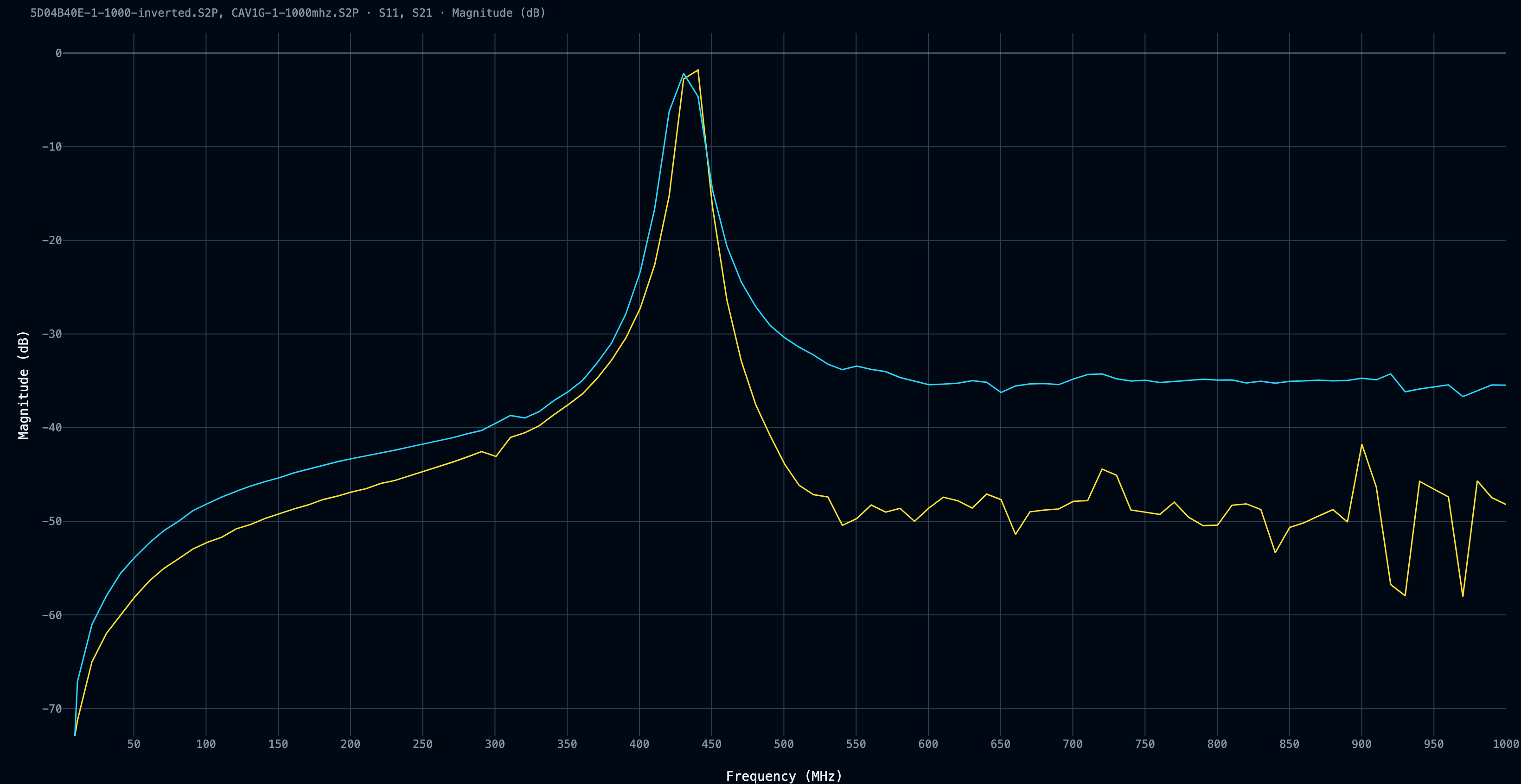
<p>The 1 MHz to 1 GHz comparison graph from the Cavity Filter V1 (blue) and the Cavity Filter V2 (yellow) shows a clear improvement on the upper side of the band. Same NanoVNA, same fixture, so whatever the absolute numbers are worth, the comparison between the two traces is valid, and V2 is straightforwardly better.</p>

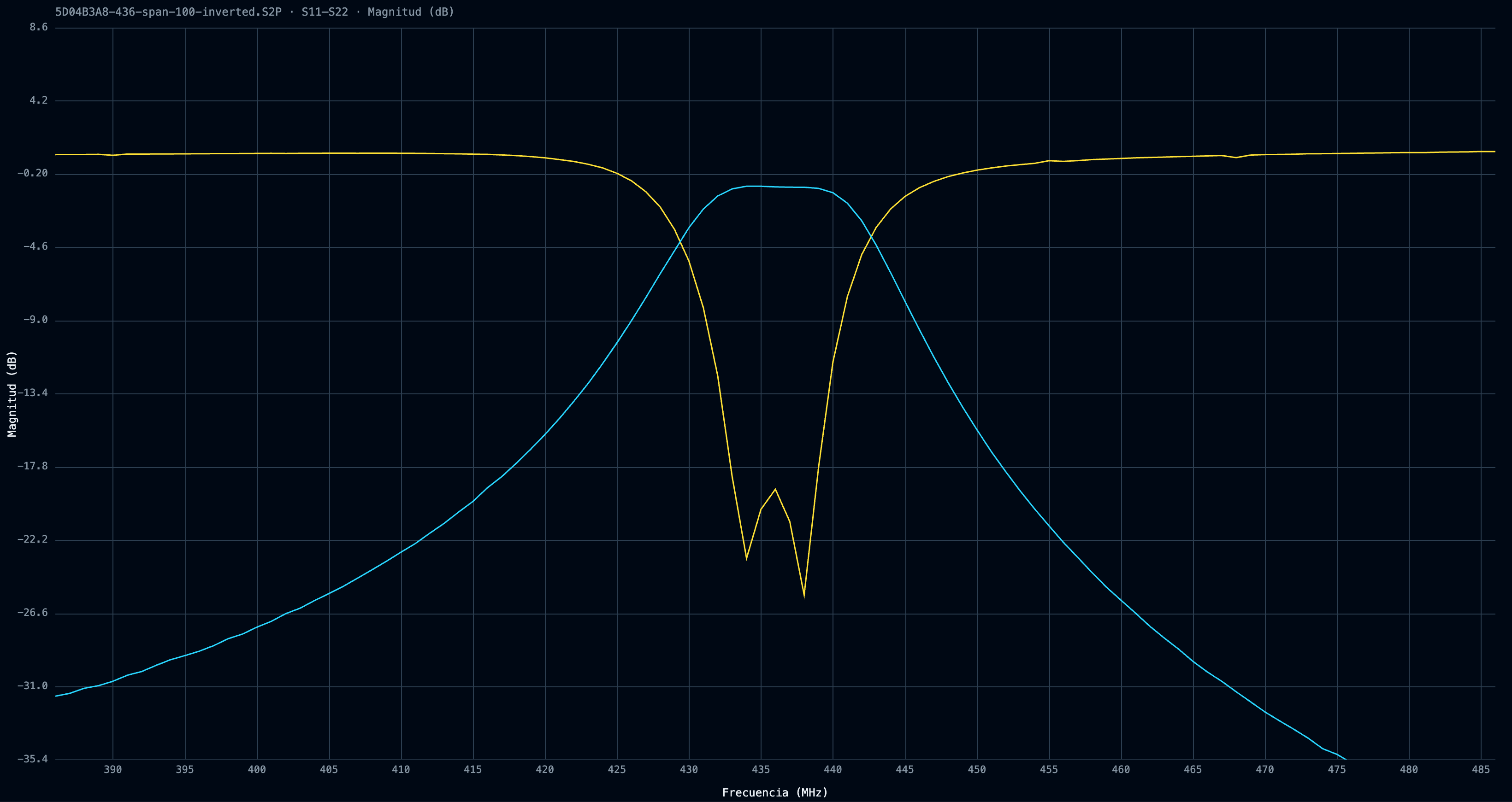
<p><a href="../assets/images/satnogs-station-1/5D04B3A8-436-span-100-inverted_db_20260813.png" target="_blank"><img src="../assets/images/satnogs-station-1/5D04B3A8-436-span-100-inverted_db_20260813.png" alt="Cavity filter v2 100MHz span" /></a></p>
<blockquote>
  <p><a href="../assets/files/satnogs-station-1/cavity-v2-436-span-100.S2P">Download the .s2p file</a></p>
</blockquote>

<p>V1’s trace flattens into a shelf on the high side, and as I mentioned earlier, a flat shelf is usually the measurement floor rather than the filter. So part of that gap is V1 leaking through an unsealed box, and part is the old setup simply being unable to resolve anything lower. Once V2 was sealed with copper tape on every seam, the trace dropped far enough to reveal rejection the earlier build couldn’t achieve, and the earlier measurement couldn’t see.</p>

<p>Both sweeps are 10 MHz per step, so treat any individual value as approximate. The raw .s2p files for both filters are available if you want to look at them yourself, along with the Python parser I used to turn <code>rtl_power</code> output into the waterfalls above.</p>

<p>S21 tells you what happens to a signal passing through something. Noise figure tells you what happens to the signal-to-noise <em>ratio</em>, because every component also adds its own thermal noise on top.</p>

<p>My filter’s dB of insertion loss is ~1 dB of noise figure. My 1.5 m of coax is another half dB or so. And because the noise added by later stages gets divided by all the gain sitting in front of them, anything <em>before</em> the first amplifier counts at full weight, while anything after it barely counts at all. Mine currently runs:</p>

<p>QFH -&gt; 1.5 m coax -&gt; filter -&gt; LNA -&gt; SDR</p>

<p>That’s roughly 1.5 dB of loss, plus the LNA’s ~0.7 dB, for a system noise figure around 2.2 dB. The SDR’s own 5-ish dB gets divided down by 20 dB of LNA gain and contributes almost nothing.</p>

<p>The better order is:</p>

<p>QFH -&gt; filter -&gt; LNA -&gt; 1.5 m coax -&gt; SDR</p>

<p>System noise figure drops to about 1.7 dB.</p>

<p>I haven’t tuned it because the filter and the LNA currently live in the sealed box with the Raspberry Pi. Moving hardware up to the mast means climbing to the terrace every time I want to change anything, and it means the thing I’m measuring changes shape between tests.</p>

<h1 id="conclusion">Conclusion</h1>

<p>This is the project I am putting more hours into recently. It is amazing to build things and have the tools to test them, in an amateur way, but testing them is.</p>

<p>So, was it worth it? I <a href="https://blog.nico.ninja/what-are-you-obsessed-with/">wrote a while ago</a> about the line between obsession that drives you and obsession that eats you. This one stayed on the good side. The trick is knowing which one you’re using before you start, and I didn’t.</p>

<p>Next steps involve moving the filter and the LNA to the antenna and seeing whether that half dB is real. Reprint the QFH in PETG at the right scale. And check whether any of this shows up in the SatNOGS observation data.</p>

<p>Feel free to schedule your favorite observations in my station: <a href="https://network.satnogs.org/stations/5042/">5042 - LU3ARN</a>!</p>]]></content><author><name>Nicolas Rey</name></author><category term="Radio" /><category term="Electronics" /><summary type="html"><![CDATA[Building a SatNOGS ground station, messing with filters and amplifiers]]></summary></entry><entry><title type="html">Flipper Zero APRS Transceiver</title><link href="https://blog.nico.ninja/flipper-zero-aprs-transceiver/" rel="alternate" type="text/html" title="Flipper Zero APRS Transceiver" /><published>2026-05-03T21:20:00+00:00</published><updated>2026-05-03T21:20:00+00:00</updated><id>https://blog.nico.ninja/flipper-zero-aprs-transceiver</id><content type="html" xml:base="https://blog.nico.ninja/flipper-zero-aprs-transceiver/"><![CDATA[<p>A few weeks ago, I stumbled upon a cool project in which <a href="https://www.yo3gnd.ro/">YO3GND</a> uses the <a href="https://github.com/yo3gnd/flipper-zero-aprs-tx">Flipper Zero’s internal CC1101 radio as an APRS UHF transmitter.</a> The C1101 radio can transmit and receive from 300 to ~1 GHz and is the core of the Flipper Zero’s Sub-GHz radio. I thought it was a very cool project, but down here in Argentina, APRS is used on VHF at 144.390 MHz.</p>

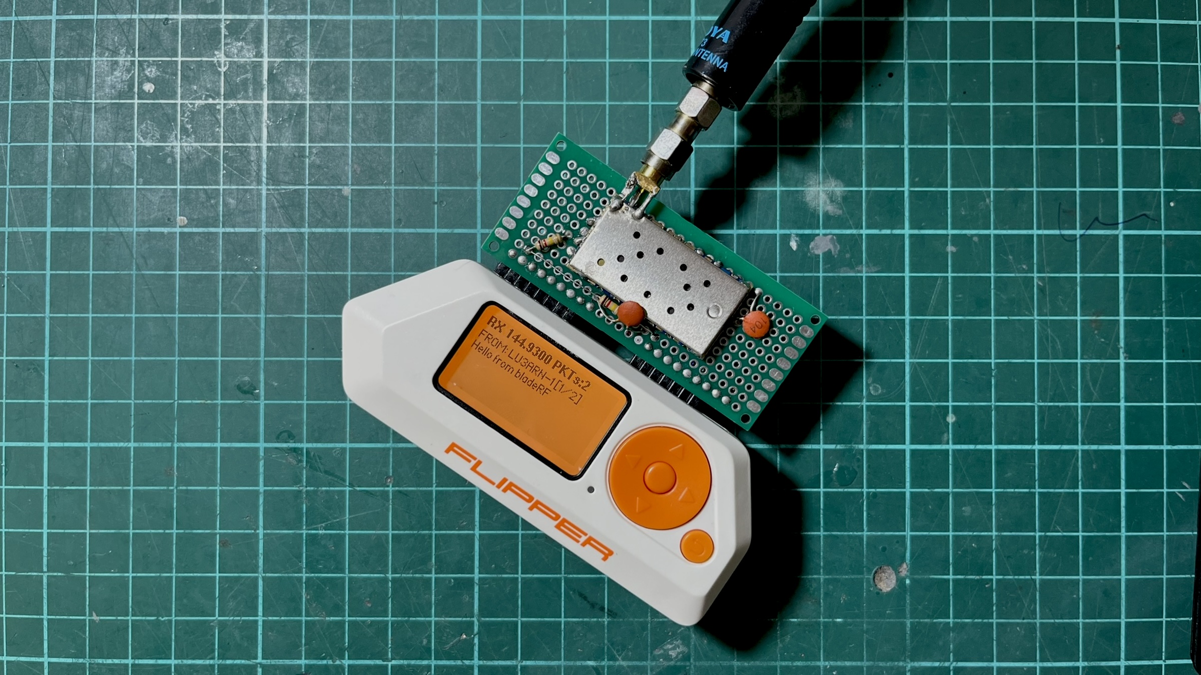
<p><a href="../assets/images/flipper-zero-aprs-trx-1/header.jpeg" target="_blank"><img src="../assets/images/flipper-zero-aprs-trx-1/header.jpeg" alt="Flipper Zero decoding APRS" /></a></p>

<p>Since I have like four or five DRA818V modules, I thought of forking off Richard’s project and porting it to use an external DRA818V module (also compatible with SA818, and their UHF versions), and as I usually do, I ended up falling through a deep hole and building a full APRS transceiver (TX and RX) for the Flipper over a few days (or probably weeks, heh).</p>

<blockquote>
  <p>The code is available at <a href="http://github.com/reynico/flipper-818-aprs">github.com/reynico/flipper-818-aprs</a></p>
</blockquote>

<ul>
  <li><a href="#transmission">Transmission</a></li>
  <li><a href="#reception">Reception</a>
    <ul>
      <li><a href="#the-bladerf-test-rig">The BladeRF test rig</a></li>
      <li><a href="#attempt-1-goertzel-demod">Attempt 1: Goertzel demod</a></li>
      <li><a href="#attempt-2-delay-and-multiply">Attempt 2: Delay-and-multiply</a></li>
      <li><a href="#the-timing-nightmare">The timing nightmare</a></li>
      <li><a href="#the-frame-dump-breakthrough">The frame dump breakthrough</a></li>
      <li><a href="#the-noise-gate-problem">The noise gate problem</a></li>
      <li><a href="#hardware-changes-that-affected-decode">Hardware changes that affected decode</a></li>
      <li><a href="#filter-polarity">Filter polarity</a></li>
      <li><a href="#tim2-isr-driven-adc-sampling">TIM2 ISR-driven ADC sampling</a></li>
    </ul>
  </li>
  <li><a href="#ui-work">UI work</a></li>
  <li><a href="#conclusion">Conclusion</a></li>
</ul>

<h1 id="transmission">Transmission</h1>

<p>Doing TX with the DRA818 module was quite straightforward. The existing AFSK waveform generator from Richard’s project produces a square wave representation of the <a href="https://www.zilog.com/docs/modem/appnotes/an0002.pdf">Bell 202 signal</a>. Instead of feeding it to the CC1101’s async TX, output it to a GPIO pin (A4), connected to the DRA818’s microphone input via a coupling cap and a resistor. The DRA818 FM-modulates and transmits it.</p>

<p><a href="../assets/images/flipper-zero-aprs-trx-1/flipper-tx-openwebrx.jpeg" target="_blank"><img src="../assets/images/flipper-zero-aprs-trx-1/flipper-tx-openwebrx.jpeg" alt="Flipper Zero TX" /></a></p>

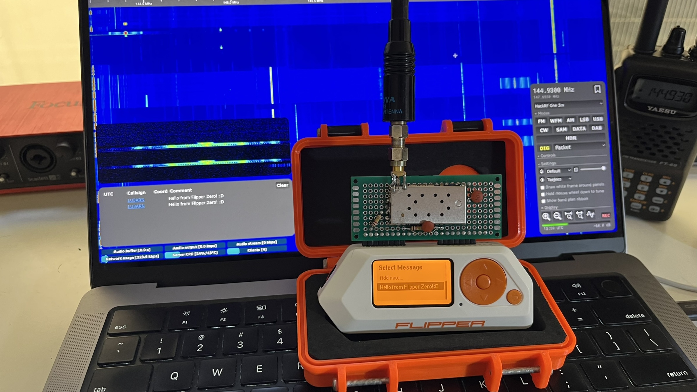
<p>Since I run my own <a href="/dual-band-openwebrx/">OpenWebRX+</a> server with an AX.25 decoder enabled, I was able to test it in just a few hours. TX was suspiciously easy (of course, because it was based on Richard’s work), but very satisfying since I was pushing around 500 mW of FM power to the air, which is like 50x more than the CC1101 internal module.</p>

<iframe loading="lazy" width="100%" height="500px" src="https://www.youtube.com/embed/i2zG8IQZOOk" frameborder="0" allowfullscreen=""></iframe>

<h1 id="reception">Reception</h1>

<p>Up to this point, I had a perfectly working and stable AX.25 transmitter, but I wanted to decode APRS traffic in real time. Since the DRA818 modules can also receive, I could do that and try to parse the audio into text with the Flipper Zero.</p>

<p>I really forgot how difficult it was to demodulate a digital signal from audio. AFSK demodulation requires reading audio samples from the DRA818’s speaker output at a precise, consistent rate of 13,200 Hz, then running a tone discriminator to determine whether each bit period contains a 1,200 Hz (mark) or 2,200 Hz (space) tone.</p>

<h2 id="the-bladerf-test-rig">The BladeRF test rig</h2>

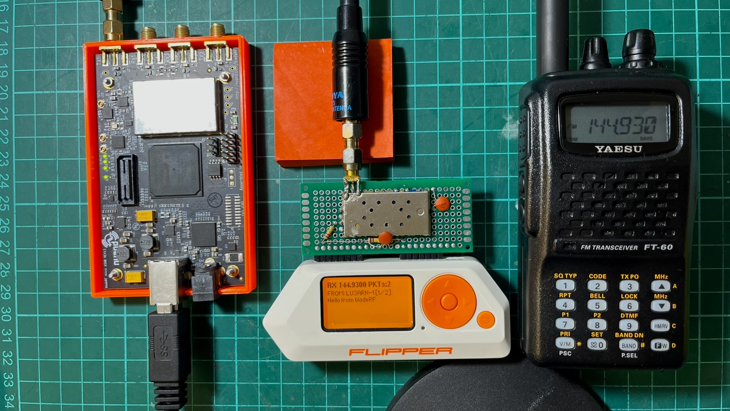
<p>While there is some APRS traffic in the city, I found it annoying trying to catch a signal and also test the demodulator, there were too many moving parts that I didn’t know if they were even moving together so I decided to use my BladeRF xA4 as an AX.25 packet generator that helped me a lot during debugging because I was able to play with messages, TX power, timing, antennas. All the tests below were performed with the BladeRF as the test rig, then moved to an open field for more realistic testing.</p>

<p><a href="../assets/images/flipper-zero-aprs-trx-1/bladerf-flipper-ft60r.jpeg" target="_blank"><img src="../assets/images/flipper-zero-aprs-trx-1/bladerf-flipper-ft60r.jpeg" alt="Flipper Zero TX and BladeRF" /></a></p>

<h2 id="attempt-1-goertzel-demod">Attempt 1: Goertzel demod</h2>

<p>After reviewing other implementations, I decided to go with a software-based <a href="https://en.wikipedia.org/wiki/Goertzel_algorithm">Goertzel demodulator</a>. Goertzel computes the energy at a single frequency efficiently. For AFSK with two known frequencies, running Goertzel twice per block and comparing magnitudes seemed to be the best approach.</p>

<p>The problem was that Goertzel is a block-based algorithm: it processes a fixed window of N samples and returns a single answer. For AFSK demodulation, you need to know where each bit starts and ends (aka clock recovery), and Goertzel blocks do not naturally align with bit boundaries. I was chopping the audio into arbitrary 11-sample chunks, hoping they’d align with the actual bits. (They didn’t).</p>

<h2 id="attempt-2-delay-and-multiply">Attempt 2: Delay-and-multiply</h2>

<p>The delay-and-multiply discriminator takes a different approach: instead of analyzing blocks, it works sample-by-sample. Each sample is multiplied by a delayed copy of itself. The DC component of the product is negative at 1,200 Hz and positive at 2,200 Hz. An <a href="https://en.wikipedia.org/wiki/Infinite_impulse_response">Infinite Impulse Response (IIR)</a> <a href="https://en.wikipedia.org/wiki/Low-pass_filter">low-pass filter</a> extracts this, and the sign indicates the tone. Unlike Goertzel, this gives a continuous discrimination signal that can be sampled at any point. Clock recovery nudges the sampling moment to align with actual bit centers. This was implemented in a worker thread using <code>furi_delay_us(68)</code> + <code>furi_hal_adc_read()</code> in a polling loop. I was polling as fast as I could and hoping the timing was consistent enough. This was an improvement over attempt 1 with a success ratio of around 20%, so it felt like progress, but not even close to reasonable by any means.</p>

<h2 id="the-timing-nightmare">The timing nightmare</h2>

<p>The polling loop’s effective sample rate depended on factors beyond the delay. It depended on everything:</p>

<ol>
  <li><code>furi_delay_us(68)</code> is a DWT busy-wait</li>
  <li>ADC read time via HAL mutex (~3-10us variable)</li>
  <li>Demodulator processing time (~5-8us varies by code path)</li>
  <li>RTOS tick preemption (1ms every ~1ms, with unpredictable duration)</li>
  <li>GUI thread draw callback timing that affected RTOS scheduling</li>
  <li>Volatile debug field writes (~5-7us, removing them broke decode)</li>
</ol>

<p>All of this added up to an effective sample rate between 11,000 and 13,000 Hz, which drifted depending on which code paths executed. The delay-and-multiply discriminator is sensitive to the sample rate because it determines the phase relationship between the signal and its delayed copy. A 5% shift was enough to flip bit decisions. Here’s where it got absurd. The worker thread included debug tracking code that used volatile writes to update ADC min/max values, LPF state, and flag counters at each iteration. Textbook throwaway instrumentation.</p>

<pre><code class="language-c">rx-&gt;dbg_adc_min = adc_min;     // volatile write
rx-&gt;dbg_adc_max = adc_max;     // volatile write
rx-&gt;dbg_mark = lpf;            // volatile float write
rx-&gt;dbg_space = mag;           // volatile float write
rx-&gt;dbg_flags++;               // volatile increment
</code></pre>

<p>These writes added about 5-8 microseconds of overhead per loop. When I removed them to “clean up” the code, the loop ran faster, the sample rate shifted by ~9%, and the demodulator stopped decoding entirely.</p>

<p>It got worse. Changing the draw function, which runs in a completely separate GUI thread, also affected the decode rate. More <code>canvas_draw_str</code> calls in the draw callback meant better decoding. Fewer calls, worse decoding. The RTOS scheduling interaction between the GUI thread and the worker thread created an indirect coupling between what was on screen and packet decoding. I was debugging a demodulator that broke when you changed the font rendering.</p>

<h2 id="the-frame-dump-breakthrough">The frame dump breakthrough</h2>

<p>I added code to dump failed frames to the Flipper’s SD card and compared byte-by-byte with the expected data:</p>

<pre><code>Expected: 82 A0 B4 8C 98 A0 60 A8 8A A6 A8 60 62 63 03 F0 3E 42...
Received: 82 A0 B4 8C 98 A0 60 28 B1 2A 98 D8 D8 00 BC 8F 10 5B...
                               ^^ first error at byte 7
</code></pre>

<p>First 7 bytes (56 bits) were perfect, then a 51.7% bit error rate due to pure random noise. The demodulator lost sync after ~47ms and never recovered. I didn’t understand whether something was flipping out the bytes just after a specific time window, or if something else was going on.</p>

<p>At this point I noticed that the script I was using in the BladeRF test rig generated audio at 22,050 Hz. <code>22050 / 1200 = 18.375</code> samples per bit, rounded to 18, producing 1225 baud (2% error). Over a 288-bit frame, this compounds to ~6 bits of drift. While not much, I thought it was corrupting the demodulator, so I fixed it by using fractional-sample accumulation, alternating between 18 and 19 samples per bit to maintain an exact 1200 baud. This hypothesis turned out to be false, but it was a good catch anyway.</p>

<h2 id="the-noise-gate-problem">The noise gate problem</h2>

<p>The demodulator had a noise gate: <code>if(|lpf| &gt; 500) process_bit()</code>. This was meant to suppress idle noise. But the LPF output has a 2f ripple component (2,400 Hz for mark). The ripple caused the LPF to cross zero multiple times per bit period, dropping the magnitude below the threshold. The gate was skipping bits at tone transitions, particularly those carrying the most information. With the gate removed, idle noise generated false frames. With it enabled, the bit drops corrupted data. The noise gate was redesigned later.</p>

<h2 id="hardware-changes-that-affected-decode">Hardware changes that affected decode</h2>

<p>For the audio input, I used two 120k/120k bias resistors (what I had on hand). The 120k resistors prevented the ADC’s sample-and-hold capacitor from fully charging, creating an unintended low-pass filter that smoothed the signal. With 10k (that seemed to be the correct impedance), the ADC read a clean, unfiltered signal that the demodulator couldn’t handle as well. I reverted to 120k to achieve natural smoothing, so I guess theory doesn’t always hit the same.</p>

<p>The first DRA818 module I picked from the radio box was one I used before for another project, and I have a bad gut feeling about it. I used it because I couldn’t remember the problem. Turns out that after a few minutes of turning it on, this first module ended up with lower audio output that clipped at the ADC maximum. This distorted waveform (effectively a square wave) worked well with the delay-and-multiply because the products had sharp transitions. Up to this point, I spent a few hours trying to understand what was going on. At the end, I just replaced the module. The replacement module had clean, symmetric audio, which produced a more ambiguous discriminator output.</p>

<p>Given the low audio output on the first module, I discovered that lowering the DRA818V volume (2-3) gave more accurate byte decoding but weaker signals. Higher volume (8) yielded stronger signals but more bit errors due to the 2f ripple. The sweet spot depended on which DRA818V module was installed, so I also added a configurable volume and squelch setting to the menu.</p>

<h2 id="filter-polarity">Filter polarity</h2>

<p>The DRA818 has configurable audio filters, de-emphasis, high-pass, and low-pass filters controlled via the <code>AT+SETFILTER</code> command. I was sending <code>AT+SETFILTER=0,0,0</code> assuming 0=off. At some point during debugging, I wondered whether that was ok, so I looked it up. The official Dorji datasheet states the opposite: 0 = on, 1 = off. The DRA818V was running with de-emphasis, high-pass, and low-pass filters all ENABLED throughout the entire debugging effort.</p>

<p>De-emphasis attenuates high frequencies on receive. For APRS, this meant the 2200 Hz space tone was attenuated relative to the 1200 Hz mark tone, creating asymmetric amplitudes that made the discriminator pattern-sensitive. These filters work really great for human voice but not for AX.25 packets. Setting <code>AT+SETFILTER=1,1,1</code> to actually disable all filters increased the decode rate from 20% to ~50%.</p>

<p>In retrospect, this (I think) explains why the first 7 bytes of each frame decoded correctly while the rest were garbage. The destination address (bytes 0-6) decodes correctly because uppercase ASCII shifted left by 1 is mark-heavy. The payload has more balanced mark/space patterns, which are more susceptible to de-emphasis distortion. Two more days of debugging spent here.</p>

<h2 id="tim2-isr-driven-adc-sampling">TIM2 ISR-driven ADC sampling</h2>

<p>Up to this point, I had decided that the polling approach was fundamentally broken. No amount of parameter tuning could overcome RTOS timing jitter. Here is the somewhat final architecture diagram that worked best for me.</p>

<p><img src="../assets/images/flipper-zero-aprs-trx-1/aprs-decoder-flow.svg" alt="APRS decoder data flow: TIM2 triggers ADC1, the ISR fills a circular buffer, and a worker thread demodulates and decodes" /></p>

<p>TIM2 triggers the ADC via hardware TRGO. The conversion starts at the exact timer tick, not when the ISR enters. ISR latency (1-2 uS) only affects the result collection, not the sample acquisition, and the sample rate is now crystal-locked at 13,201 Hz (~0.01% error).</p>

<p>The choice of 13,200 Hz was deliberate. It divides evenly into 1,200 baud, yielding exactly 11 samples per bit, so I avoid fractional accumulation and thus avoid drift. The demodulator parameters are now deterministic and don’t change when the code is modified, so enabling or disabling debug mode or drawing the screen won’t affect decoding.</p>

<p>The worker thread is now fully decoupled from timing, it sleeps via <code>furi_thread_flags_wait</code> and wakes when samples are available, processes them in bursts, then sleeps again. This way, I avoid <code>furi_delay_us</code> and busy polling.</p>

<p>The noise gate needed a redesign. The old gate skipped individual bit decisions when the LPF magnitude fell below the threshold, which occurred at every tone transition. The new gate separates carrier detection from bit processing:</p>

<pre><code class="language-c">// Per-sample: track carrier
if(mag &gt; threshold) { carrier_present = true; silence_count = 0; }
else { silence_count++; if(silence_count &gt; 220) carrier_present = false; }

// Per-bit: only at decision point
if(bit_phase &gt;= 11) {
    if(carrier_present) { /* decode bit, process AX.25 */ }
}
</code></pre>

<p>Once the carrier is detected, ALL bits are processed regardless of instantaneous LPF magnitude dips. After 20-bit periods of silence, reset to the hunt state. This achieved a 100% success rate in decoding AX.25 packets, even under harsh conditions with a low signal-to-noise ratio.</p>

<iframe loading="lazy" width="100%" height="500px" src="https://www.youtube.com/embed/M0hjUN8xKgM" frameborder="0" allowfullscreen=""></iframe>

<h1 id="ui-work">UI work</h1>

<p>Since I forked off Richard’s project, I integrated my DRA818 work into the UI Richard designed, but quickly realized it wouldn’t work because everything was built to support both C1101 and DRA818; both modules require different configuration settings, and behave differently. Since this project evolved into building an APRS transceiver, I decided to remove the CC1101 settings and stick with the DRA818 settings.</p>

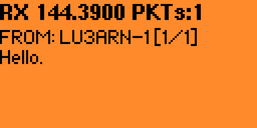
<p><a href="../assets/images/flipper-zero-aprs-trx-1/rx.png" target="_blank"><img src="../assets/images/flipper-zero-aprs-trx-1/rx.png" alt="RX, debug disabled" /></a></p>

<p>The reception screen accepts multiple multi-page messages, so you can read large messages and also read older ones. Messages are not stored anywhere else, but I might add SD card logging later.</p>

<p>The settings view allows configuring the frequency from a list of default options, including a custom frequency, configuring TX lead-in and preamble times to avoid laggy receivers missing packets, RX volume and squelch level, enabling haptics (sound and vibration) when a message is successfully decoded, which is handy when you are not checking the Flipper’s screen, and debug screens for transmission and reception that helped me a lot to check what was going on, especially during reception of messages.</p>

<p><a href="../assets/images/flipper-zero-aprs-trx-1/rx-debug-on.png" target="_blank"><img src="../assets/images/flipper-zero-aprs-trx-1/rx-debug-on.png" alt="RX, debug enabled" /></a></p>

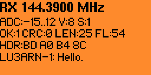
<p>The debug RX screen shows the demodulator’s internal state in real time. ADC is the raw signal amplitude range. During a packet, you’ll see it swing wide (e.g., -500..480), during silence, it stays near zero. V and S are the current DRA818 volume and squelch settings. OK counts successfully decoded packets, CRC counts frames that were assembled but failed the checksum. A high CRC count with zero OK means the demodulator is close, but the bit accuracy isn’t there yet. LEN is the byte length of the last attempted frame. FL counts detected AX.25 flag bytes (0x7E). These mark frame boundaries, so a high flag count confirms the demodulator is at least finding the preamble.</p>

<h1 id="conclusion">Conclusion</h1>

<p>TX is solid,  <a href="/dual-band-openwebrx/">OpenWebRX+</a> decodes packets with no effort. RX hits 100% on bench tests and picks up real APRS traffic in the field, though the DRA818’s receiver sensitivity is the weak point. The module has no front-end LNA, so it relies purely on antenna gain and signal strength. I’m planning to add an <a href="../assets/images/improving-filtering-sdr-1/SPF5189Z.PDF">SPF5189Z</a> low-noise amplifier on the receive path, switched out during TX via a MOSFET on the PTT line. The code is available at <a href="http://github.com/reynico/flipper-818-aprs">github.com/reynico/flipper-818-aprs</a></p>]]></content><author><name>Nicolas Rey</name></author><category term="Radio" /><category term="Electronics" /><summary type="html"><![CDATA[Building a APRS transceiver out of a Flipper Zero and a DRA818V module]]></summary></entry><entry><title type="html">Improving filtering in my SDR receiver</title><link href="https://blog.nico.ninja/improving-filtering-openwebrx/" rel="alternate" type="text/html" title="Improving filtering in my SDR receiver" /><published>2026-04-17T21:30:00+00:00</published><updated>2026-04-17T21:30:00+00:00</updated><id>https://blog.nico.ninja/improving-filtering-openwebrx</id><content type="html" xml:base="https://blog.nico.ninja/improving-filtering-openwebrx/"><![CDATA[<p>A while ago, I built and made available a <a href="/dual-band-openwebrx/">dual-band VHF/UHF OpenWebRX+ Internet SDR receiver</a>, <a href="https://sdr.nico.ninja">https://sdr.nico.ninja</a>. Time passed, and things changed. I replaced both <a href="http://RTL-SDR.com">RTL-SDR.com</a> v3 SDR receivers with my old, unused HackRF One. I also decided to cover just the VHF ham radio band, from 144 to 148 MHz (and a bit more on each edge), since most hams around here are most active on the 2-meter band.</p>

<p>Also, with the installation of my HF shack, I moved my antennae to the building’s terrace, took advantage of the space up there, and moved the SDR and antenna.</p>

<p>Not much surprise to me, the HackRF One is a hell of a waterfall full of noise, nevertheless I wasn’t too hooked to the 2m band, so I left it as it was, noisy, but with a nice antenna deployment, 50 meters above sea level.</p>

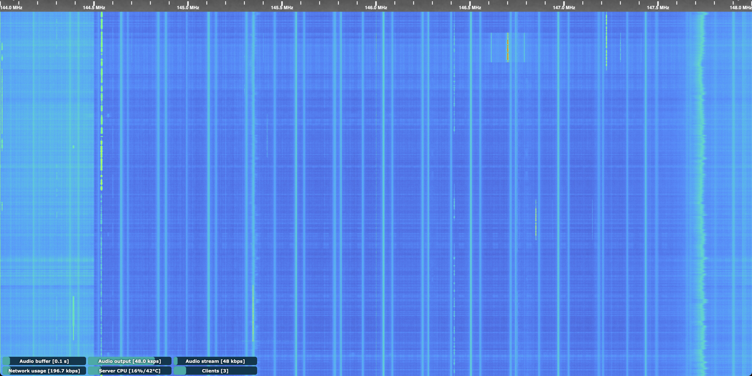
<p><a href="../assets/images/improving-filtering-sdr-1/before.jpg" target="_blank"><img src="../assets/images/improving-filtering-sdr-1/before.jpg" alt="Noise figure in OpenWebRX+" /></a></p>

<p>A few weeks ago, I decided to investigate further into the noisy figure of my SDR. Despite many people complaining that the HackRF board is noisy by design and prone to inducing <a href="https://github.com/greatscottgadgets/hackrf/issues/544">interference from one of the internal clocks</a>. Moving down the gain controls a bit didn’t do much, really, as you can see in the following screenshot.</p>

<p><a href="../assets/images/improving-filtering-sdr-1/reduce-gain.jpg" target="_blank"><img src="../assets/images/improving-filtering-sdr-1/reduce-gain.jpg" alt="Lowering the gain has no effect in noise" /></a></p>

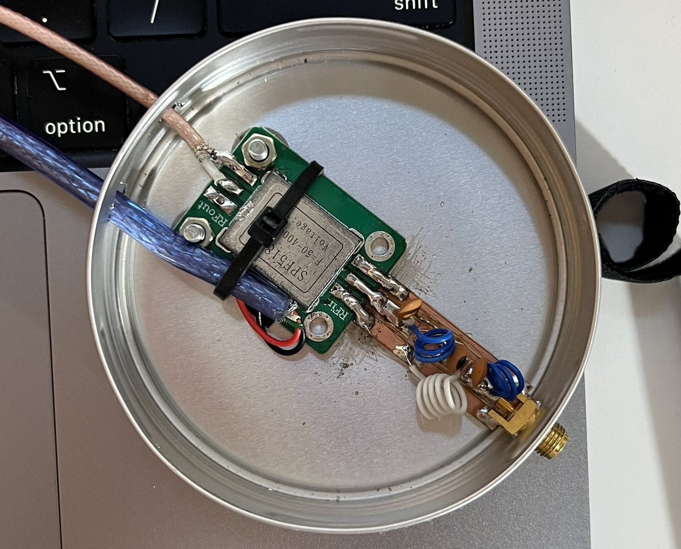
<p>But I found that setting the LNA gain to 0 and adjusting the VGA gain reduced much of the internally induced noise. So I thought I could hook up an <a href="../assets/images/improving-filtering-sdr-1/SPF5189Z.PDF">SPF5189Z</a> LNA I had in my radio box. Coupled with the homemade FM band-stop filter, this should do a pretty good job. Even better, I also added several ferrite beads to the USB and coaxial cables.</p>

<p><a href="../assets/images/improving-filtering-sdr-1/lna-and-filter.jpg" target="_blank"><img src="../assets/images/improving-filtering-sdr-1/lna-and-filter.jpg" alt="LNA and filter" /></a></p>

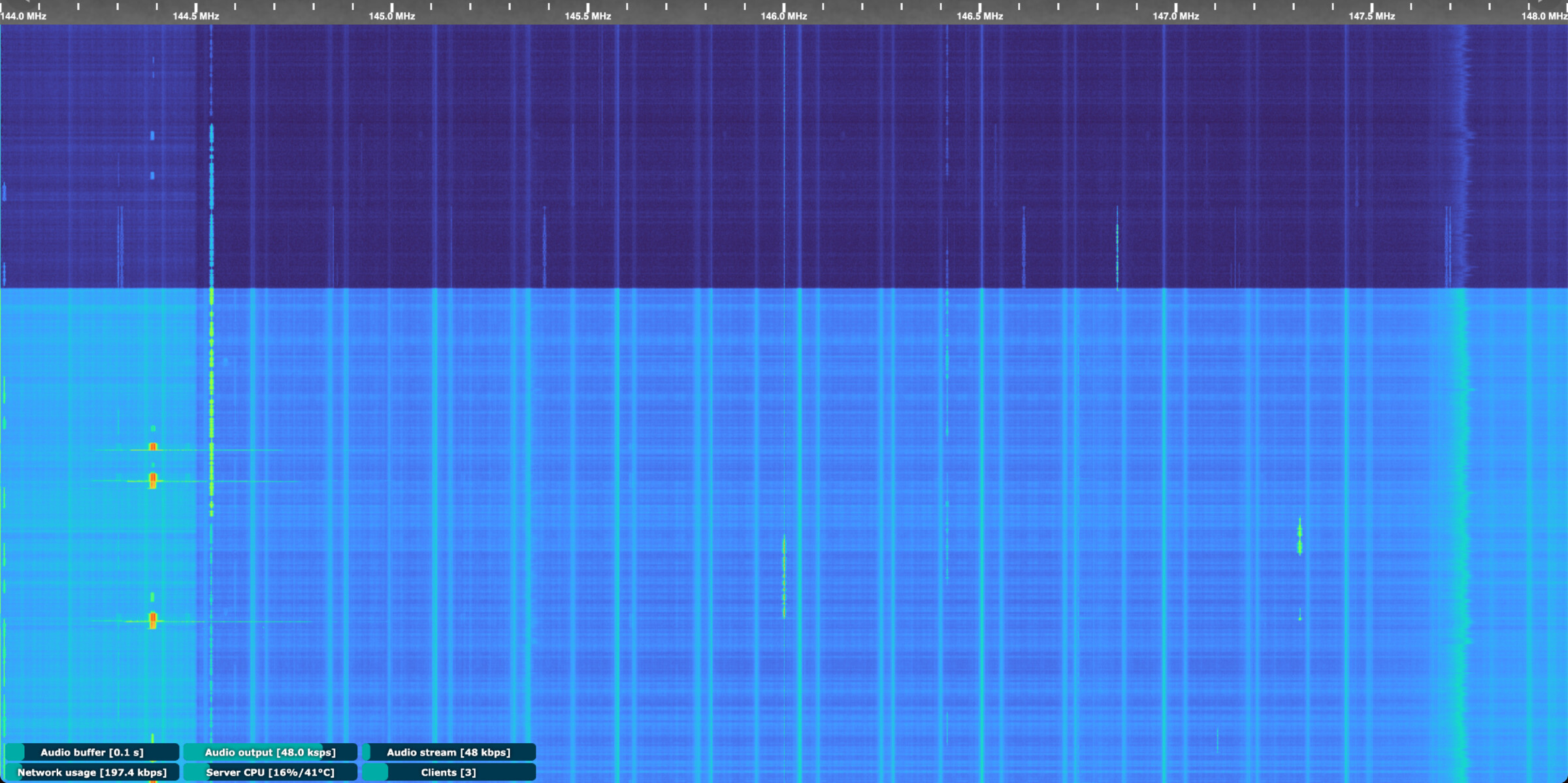
<p>And indeed that was it.</p>

<p><a href="../assets/images/improving-filtering-sdr-1/after.jpg" target="_blank"><img src="../assets/images/improving-filtering-sdr-1/after.jpg" alt="Current noise figure" /></a></p>

<p>Although I still run the SDR with the not-so-good Flower Pot antenna, it works very well, I guess, due to the high elevation in this zone.</p>

<p>Next steps: replace the Flower Pot with something vertical and omnidirectional with higher gain, and modify the <a href="../assets/images/improving-filtering-sdr-1/SPF5189Z.PDF">SPF5189Z</a> to feed it through a bias-tee.</p>]]></content><author><name>Nicolas Rey</name></author><category term="Radio" /><category term="Electronics" /><summary type="html"><![CDATA[Reducing the noise figure when working with the HackRF One]]></summary></entry><entry><title type="html">RadioBerry on a Yaesu FT-80C</title><link href="https://blog.nico.ninja/radioberry-yaesu-ft80c-1/" rel="alternate" type="text/html" title="RadioBerry on a Yaesu FT-80C" /><published>2026-02-04T21:30:00+00:00</published><updated>2026-02-04T21:30:00+00:00</updated><id>https://blog.nico.ninja/radioberry-yaesu-ft80c-1</id><content type="html" xml:base="https://blog.nico.ninja/radioberry-yaesu-ft80c-1/"><![CDATA[<blockquote>
  <p>A note for the readers: This project is fully documented (from a technical perspective) in <a href="https://github.com/reynico/radioberry-setup">reynico/radioberry-setup</a></p>
</blockquote>

<p>Shortly after finishing the <a href="/radioberry-vertex-vx1700-1/">Vertex VX1700 RadioBerry build</a>, my dad showed up at the workshop with a Yaesu FT-80C he had stored away for years. The radio was fully working - nothing wrong with it - but it was just sitting there unused. “What if we turn this one into a RadioBerry too?” he asked.</p>

<p>The FT-80C (also sold as FT-747GX) is a classic late-80s HF transceiver. Unlike the VX1700, where I built a completely new front panel with a touchscreen, this time I wanted to preserve the original look. The challenge was clear: make the RadioBerry control everything while keeping the radio looking exactly like it did 35 years ago, ensuring aesthetic integrity while adding modern functionality.</p>

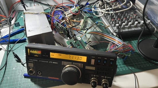
<p><a href="../assets/images/radioberry-ft80c-1/header.jpg" target="_blank"><img src="../assets/images/radioberry-ft80c-1/header.jpg" alt="FT-80C with RadioBerry installed" /></a></p>

<p>The process of building four boards, reverse engineering the display, and integrating controls was challenging, but sharing this journey aims to inspire your own projects.</p>

<h2 id="table-of-contents">Table of contents</h2>

<ul>
  <li><a href="#table-of-contents">Table of contents</a></li>
  <li><a href="#first-steps-understanding-what-i-had">First steps: understanding what I had</a></li>
  <li><a href="#lpf-control-and-tx-switching">LPF Control and TX switching</a></li>
  <li><a href="#midi-controller-for-the-front-panel">MIDI Controller for the front panel</a>
    <ul>
      <li><a href="#button-mapping">Button mapping</a></li>
    </ul>
  </li>
  <li><a href="#lcd-controller">LCD Controller</a>
    <ul>
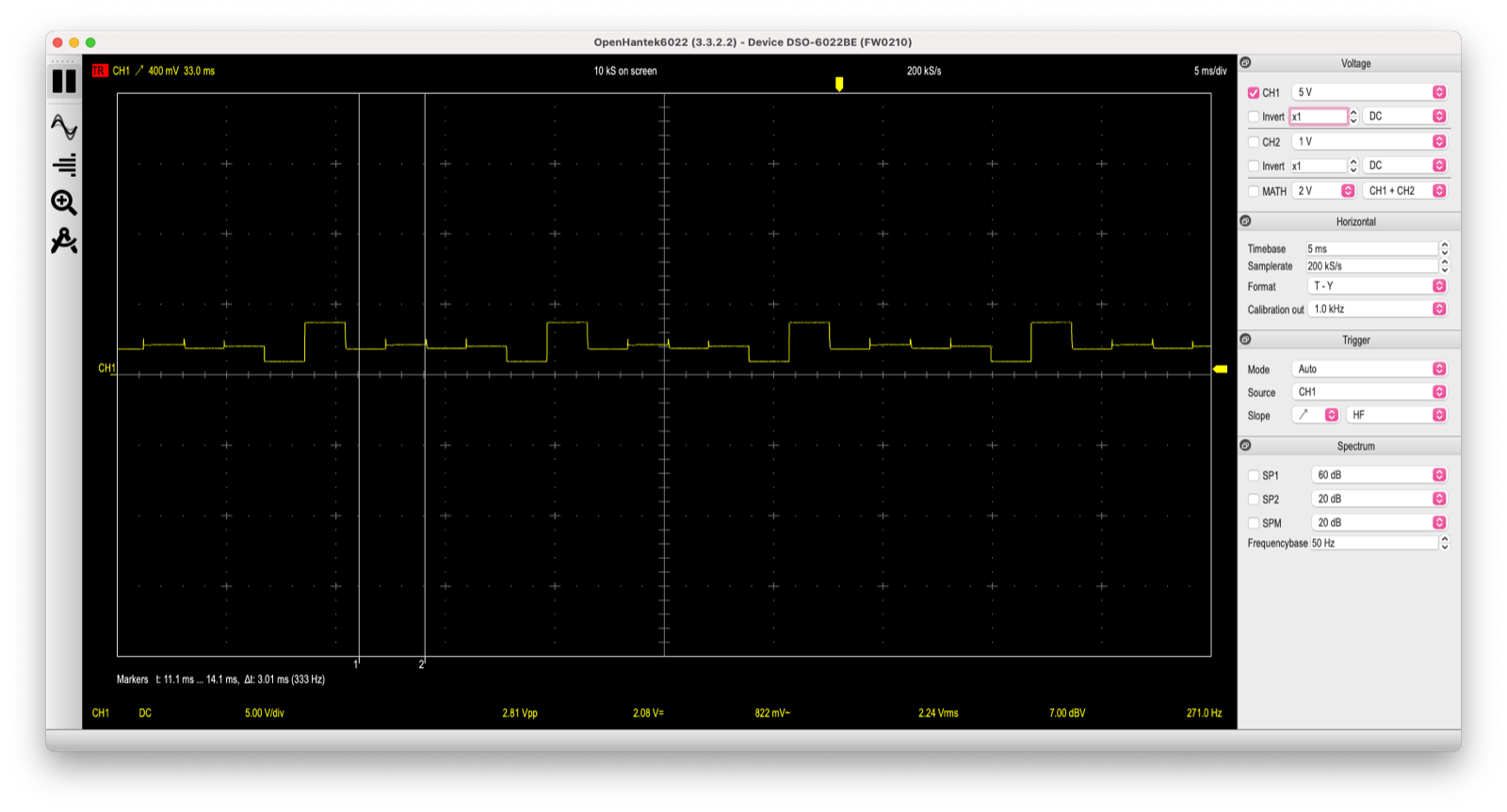
      <li><a href="#reverse-engineering-the-original-controller">Reverse engineering the original controller</a></li>
      <li><a href="#finding-the-ht1621b">Finding the HT1621B</a></li>
      <li><a href="#wiring-35-connections">Wiring 35 connections</a></li>
      <li><a href="#mapping-128-segments">Mapping 128 segments</a></li>
      <li><a href="#connecting-to-pihpsdr">Connecting to piHPSDR</a></li>
      <li><a href="#s-meter">S-meter</a></li>
    </ul>
  </li>
  <li><a href="#power-supply-and-soft-shutdown">Power Supply and Soft Shutdown</a>
    <ul>
      <li><a href="#voltage-regulation">Voltage regulation</a></li>
      <li><a href="#soft-shutdown-circuit">Soft shutdown circuit</a></li>
      <li><a href="#mounting-everything">Mounting everything</a></li>
    </ul>
  </li>
  <li><a href="#putting-it-all-together">Putting it all together</a></li>
  <li><a href="#3d-printed-front-panel-buttons">3D Printed Front Panel Buttons</a></li>
  <li><a href="#the-7-lcd-display-challenge">The 7” LCD Display Challenge</a></li>
  <li><a href="#frequency-calibration-from-hz-to-ppm">Frequency calibration: from Hz to PPM</a></li>
  <li><a href="#remote-control-and-digital-modes">Remote control and digital modes</a></li>
  <li><a href="#lessons-learned">Lessons learned</a></li>
</ul>

<h2 id="first-steps-understanding-what-i-had">First steps: understanding what I had</h2>

<p>Before touching anything, I spent a couple of evenings just studying the radio. The <a href="../assets/files/radioberry-ft80c-1/ft-80c-service-manual.pdf">FT-80C service manual</a> was helpful. What I did have was:</p>

<ul>
  <li>A working PA stage capable of 100W output</li>
  <li>Six low-pass filters on the LPF board, with their relay drivers intact</li>
  <li>The original LCD display (a mysterious custom part labeled FTD8627PZ)</li>
  <li>All front panel controls are in working condition</li>
</ul>

<p><a href="../assets/images/radioberry-ft80c-1/ft80c-initial-open.jpeg" target="_blank"><img src="../assets/images/radioberry-ft80c-1/ft80c-initial-open.jpeg" alt="FT-80C top view" /></a></p>

<p>The plan was to use the RadioBerry as the brain, feeding its output (about 100-150mW) into the existing PA stage. The tricky part would be controlling everything else: filter selection, TX/RX switching, the display, and all those buttons.</p>

<p>I approached this in stages, building and testing each board individually, hoping to show you that a methodical process can lead to reliable results.</p>

<h2 id="lpf-control-and-tx-switching">LPF Control and TX switching</h2>

<p>The first board I built handles the low-pass filter selection and TX/RX switching. In the original radio, a BCD-to-decimal decoder on the main board drives the filter relays. Since I removed the main board, I needed a replacement.</p>

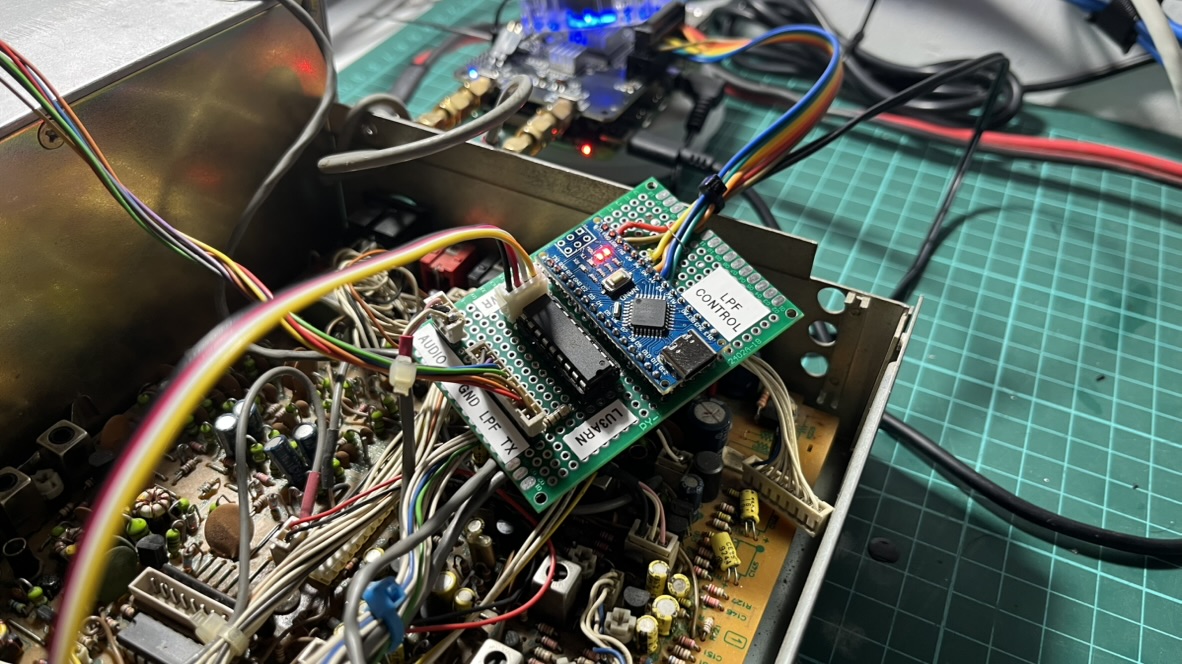
<p>An Arduino Nano was perfect for this. It emulates an <a href="https://openhpsdr.org/alex.php">Alex filter board</a> (the standard filter interface for HPSDR projects) by listening on I2C address <code>0x21</code>. When the RadioBerry changes bands, it sends a command, and the Arduino activates the corresponding filter relay.</p>

<p><a href="../assets/images/radioberry-ft80c-1/radioberry-lpf-control-separate.jpeg" target="_blank"><img src="../assets/images/radioberry-ft80c-1/radioberry-lpf-control-separate.jpeg" alt="RadioBerry connected to LPF Control board" /></a></p>

<p>The FT-80C has 6 filters covering all HF bands. Since I’m driving them directly (not through the original BCD decoder), I use a <a href="../assets/files/radioberry-ft80c-1/UDN2981.pdf">UDN2981</a> source driver. It’s basically the PNP version of the popular ULN2003 - each output can sink the ~40mA the filter relays need.</p>

<table>
  <thead>
    <tr>
      <th>Band</th>
      <th>Alex Command</th>
      <th>Arduino Pin</th>
      <th>Filter</th>
      <th>Frequency</th>
    </tr>
  </thead>
  <tbody>
    <tr>
      <td>160M</td>
      <td>1608</td>
      <td>D8</td>
      <td>LPF1</td>
      <td>1.8 MHz</td>
    </tr>
    <tr>
      <td>80M</td>
      <td>1604</td>
      <td>D7</td>
      <td>LPF2</td>
      <td>3.5 MHz</td>
    </tr>
    <tr>
      <td>60M</td>
      <td>1602</td>
      <td>D6</td>
      <td>LPF3</td>
      <td>7 MHz</td>
    </tr>
    <tr>
      <td>40M</td>
      <td>802</td>
      <td>D6</td>
      <td>LPF3</td>
      <td>7 MHz</td>
    </tr>
    <tr>
      <td>30M</td>
      <td>401</td>
      <td>D5</td>
      <td>LPF4</td>
      <td>10/14 MHz</td>
    </tr>
    <tr>
      <td>20M</td>
      <td>101</td>
      <td>D5</td>
      <td>LPF4</td>
      <td>14 MHz</td>
    </tr>
    <tr>
      <td>17M</td>
      <td>164</td>
      <td>D4</td>
      <td>LPF5</td>
      <td>18/21 MHz</td>
    </tr>
    <tr>
      <td>15M</td>
      <td>264</td>
      <td>D4</td>
      <td>LPF5</td>
      <td>21 MHz</td>
    </tr>
    <tr>
      <td>12M</td>
      <td>232</td>
      <td>D3</td>
      <td>LPF6</td>
      <td>24.5/28</td>
    </tr>
    <tr>
      <td>10M</td>
      <td>232</td>
      <td>D3</td>
      <td>LPF6</td>
      <td>28 MHz</td>
    </tr>
  </tbody>
</table>

<p>The same board also handles PTT. The RadioBerry’s PTT output is active-low at 3.3V. Still, the TX relay on the LPF board expects around 7.5V (I measured the original circuit). A 180 ohm series resistor drops the 13.8V down to the right level for the relay coil.</p>

<p><a href="../assets/images/radioberry-ft80c-1/lpf-control-mounted.jpeg" target="_blank"><img src="../assets/images/radioberry-ft80c-1/lpf-control-mounted.jpeg" alt="LPF Control board mounted in the radio" /></a></p>

<p>I labeled the board “LPF CONTROL” with a piece of tape - not the most professional approach, but it helps when you’re debugging at 2am and can’t remember which board does what.</p>

<p>The first time I powered everything up and heard the relays clicking as I changed bands in piHPSDR, it felt like real progress.</p>

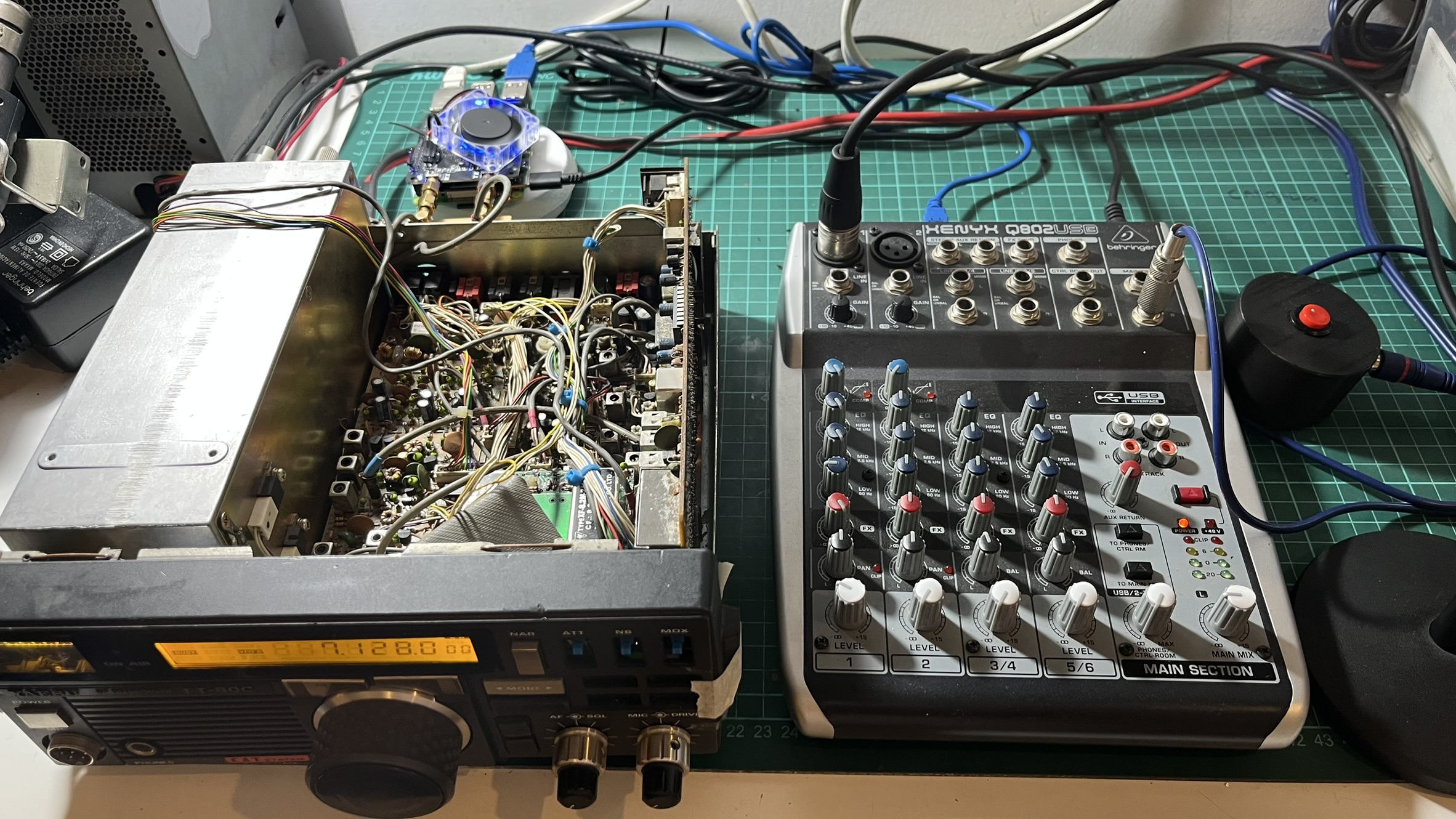
<p>At this point, I started actually using the radio. I connected an AKG D5 microphone through a Behringer Q802 mixer via USB for audio input. The audio quality was impressive - the combination of a decent dynamic mic and the RadioBerry’s clean signal path made for really nice SSB audio.</p>

<p><a href="../assets/images/radioberry-ft80c-1/ft80c-with-mixer.jpeg" target="_blank"><img src="../assets/images/radioberry-ft80c-1/ft80c-with-mixer.jpeg" alt="FT-80C with Behringer mixer" /></a></p>

<h2 id="midi-controller-for-the-front-panel">MIDI Controller for the front panel</h2>

<p>The FT-80C front panel has 15 buttons, 3 potentiometers, and a rotary encoder for tuning. I needed a way to interface all of these with piHPSDR.</p>

<p>Fortunately, piHPSDR has excellent MIDI support. Any MIDI controller can be mapped to virtually any function in the software. This made the Raspberry Pi Pico RP2040 the obvious choice - it can easily emulate a USB MIDI device using CircuitPython.</p>

<p><a href="../assets/images/radioberry-ft80c-1/ft80c-buttons-panel.jpeg" target="_blank"><img src="../assets/images/radioberry-ft80c-1/ft80c-buttons-panel.jpeg" alt="FT-80C front panel with buttons" /></a></p>

<p>The wiring was tedious but straightforward. Each button connects between a GPIO pin and ground, using the Pico’s internal pull-up resistors. When you press a button, the pin goes low, and the code sends a MIDI Note On message. Release the button, Note Off.</p>

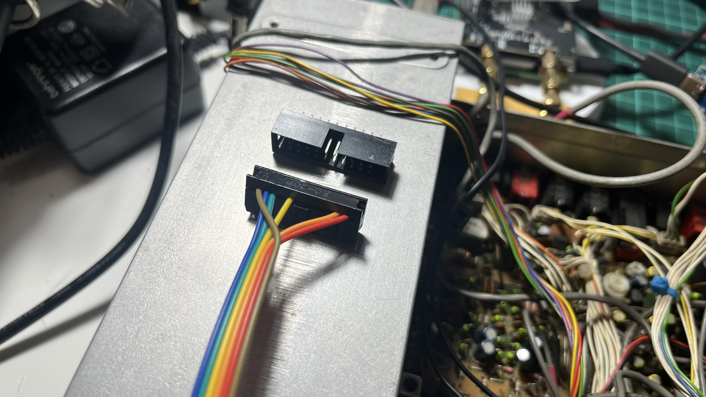
<p>I used a 20-pin IDC connector to interface with the Pico. This way, I don’t have to solder directly onto the board every time I need to make changes - just crimp a new ribbon cable. It also means I can swap out the Pico without desoldering anything if something goes wrong.</p>

<h3 id="button-mapping">Button mapping</h3>

<table>
  <thead>
    <tr>
      <th>Button</th>
      <th>GPIO</th>
      <th>MIDI Note</th>
      <th>piHPSDR Function</th>
    </tr>
  </thead>
  <tbody>
    <tr>
      <td>NARROW</td>
      <td>GP0</td>
      <td>1</td>
      <td>Filter width</td>
    </tr>
    <tr>
      <td>ATT</td>
      <td>GP1</td>
      <td>2</td>
      <td>Attenuator</td>
    </tr>
    <tr>
      <td>NOISE BLANKER</td>
      <td>GP2</td>
      <td>3</td>
      <td>NB toggle</td>
    </tr>
    <tr>
      <td>MODE &lt;</td>
      <td>GP15</td>
      <td>4</td>
      <td>Mode down</td>
    </tr>
    <tr>
      <td>MODE &gt;</td>
      <td>GP16</td>
      <td>5</td>
      <td>Mode up</td>
    </tr>
    <tr>
      <td>VFO &gt; M</td>
      <td>GP5</td>
      <td>6</td>
      <td>VFO to Memory</td>
    </tr>
    <tr>
      <td>M &gt; VFO</td>
      <td>GP6</td>
      <td>7</td>
      <td>Memory to VFO</td>
    </tr>
    <tr>
      <td>VFO</td>
      <td>GP7</td>
      <td>8</td>
      <td>VFO select</td>
    </tr>
    <tr>
      <td>MR</td>
      <td>GP8</td>
      <td>9</td>
      <td>Memory recall</td>
    </tr>
    <tr>
      <td>SPLIT</td>
      <td>GP9</td>
      <td>10</td>
      <td>Split mode</td>
    </tr>
    <tr>
      <td>PRI-M</td>
      <td>GP10</td>
      <td>11</td>
      <td>Priority memory</td>
    </tr>
    <tr>
      <td>FAST</td>
      <td>GP11</td>
      <td>12</td>
      <td>Fast tuning</td>
    </tr>
    <tr>
      <td>BAND</td>
      <td>GP12</td>
      <td>13</td>
      <td>Band change</td>
    </tr>
    <tr>
      <td>CLAR</td>
      <td>GP13</td>
      <td>14</td>
      <td>Clarifier</td>
    </tr>
    <tr>
      <td>D LOCK</td>
      <td>GP14</td>
      <td>15</td>
      <td>Dial lock</td>
    </tr>
  </tbody>
</table>

<p>The three potentiometers (SQL, MIC gain, DRIVE) connect to the Pico’s ADC pins and send MIDI Control Change messages. I added some filtering in the software to prevent noise from generating spurious MIDI events - a threshold of about 512 ADC units works well.</p>

<p>The VFO encoder was interesting. The original encoder still worked perfectly after 35 years, so I just wired it to GP3 and GP4. The code sends relative MIDI CC values: 63 for counter-clockwise, 65 for clockwise. piHPSDR interprets these as tuning commands.</p>

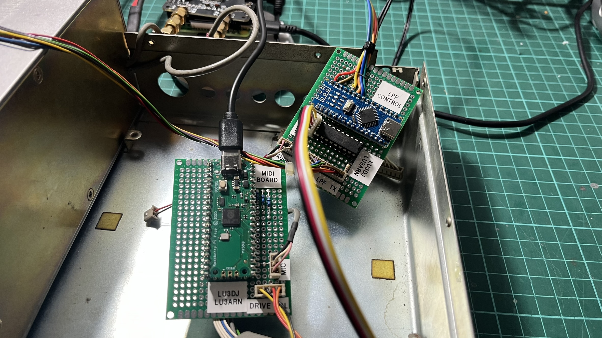
<p><a href="../assets/images/radioberry-ft80c-1/midi-lpf-boards-mounted.jpeg" target="_blank"><img src="../assets/images/radioberry-ft80c-1/midi-lpf-boards-mounted.jpeg" alt="MIDI board and LPF Control board installed" /></a></p>

<p>With the LPF and MIDI controllers done, the radio was starting to feel alive. You could change bands, tune around, switch modes - all using the original knobs and buttons. But the display was still dark.</p>

<h2 id="lcd-controller">LCD Controller</h2>

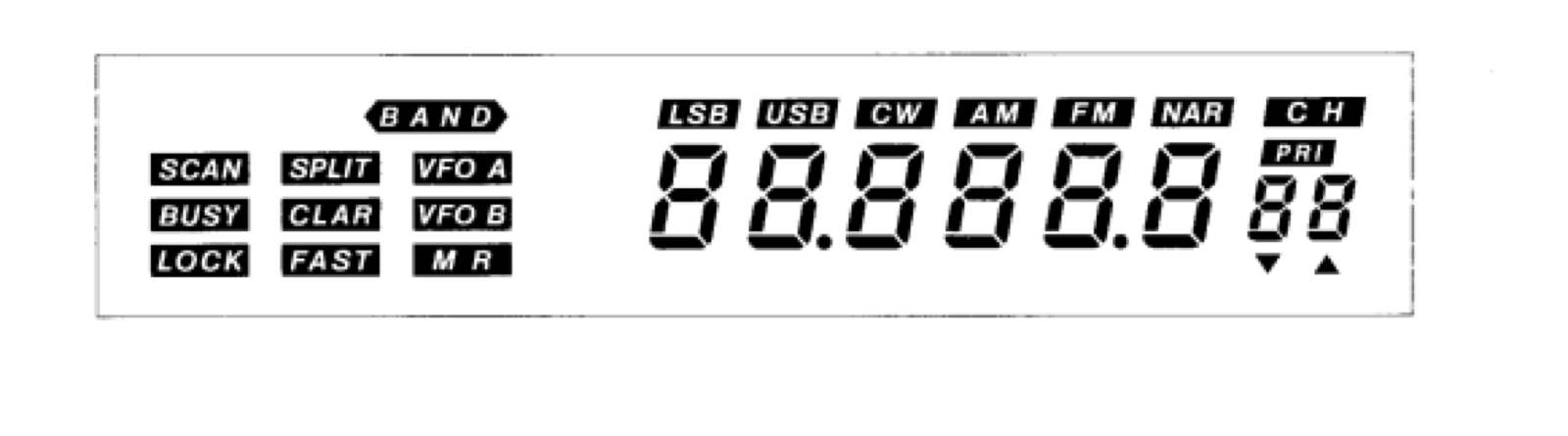
<p>This is where I fell into a rabbit hole. The FT-80C uses a custom LCD display (FTD8627PZ) driven by a Mitsubishi <a href="../assets/files/radioberry-ft80c-1/M50930.pdf">M50932</a> microcontroller with integrated LCD driver. There’s essentially no documentation available for this display - it’s a Yaesu proprietary part.</p>

<p><a href="../assets/images/radioberry-ft80c-1/lcd-segments-diagram.png" target="_blank"><img src="../assets/images/radioberry-ft80c-1/lcd-segments-diagram.png" alt="LCD segments diagram" /></a></p>

<p>The display shows frequency (7 digits), operating mode (LSB, USB, CW, AM, FM), and various indicators (VFO A/B, SPLIT, LOCK, etc.). I really wanted to keep using it - replacing it with a generic LCD would have ruined the look of the radio.</p>

<p>Before diving into the hardware, I had to understand how these multiplexed LCD displays actually work. Unlike LEDs, which you can just drive with DC, LCD segments need to be driven with AC signals. If you apply a constant DC voltage to an LCD segment, the liquid crystals will eventually degrade, permanently damaging the display. The controller has to continuously alternate the voltage polarity on each segment, typically at 30-60Hz. This is why you can’t just “turn on” a segment with a GPIO pin - you need a proper LCD driver that handles the AC waveform generation.</p>

<h3 id="reverse-engineering-the-original-controller">Reverse engineering the original controller</h3>

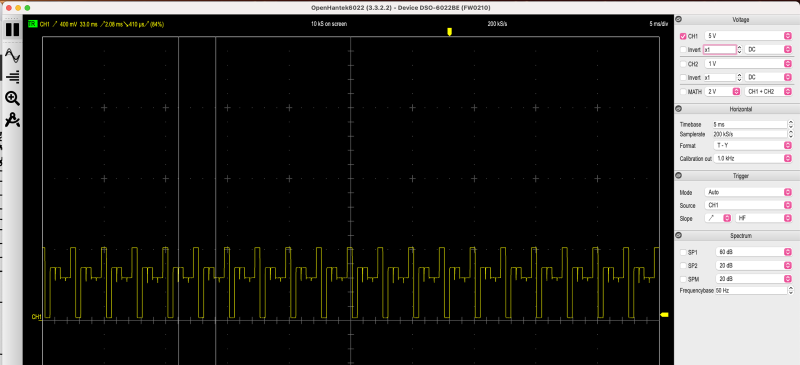
<p>The first step was understanding how the M50932 drives the display. I connected an oscilloscope to the COM and SEG lines. In contrast, the original board was still connected (powered by a bench supply).</p>

<p><a href="../assets/images/radioberry-ft80c-1/oscilloscope-m50932.png" target="_blank"><img src="../assets/images/radioberry-ft80c-1/oscilloscope-m50932.png" alt="Original M50932 signal capture" /></a></p>

<p>The captures told me what I needed to know:</p>
<ul>
  <li><strong>Bias</strong>: 1/3 (three voltage levels visible in the waveform)</li>
  <li><strong>Duty cycle</strong>: 1/3 (using 3 COM lines)</li>
  <li><strong>Frame rate</strong>: approximately 30Hz</li>
</ul>

<p>Armed with this information, I set out to find a replacement LCD driver that met these parameters.</p>

<h3 id="finding-the-ht1621b">Finding the HT1621B</h3>

<p>After some research, I found the <a href="../assets/files/radioberry-ft80c-1/ht1621b.PDF">HT1621B</a> from Holtek. It’s a RAM-mapped LCD driver with a serial interface, capable of driving up to 32 segments x 4 commons. The specs matched my requirements almost perfectly:</p>

<table>
  <thead>
    <tr>
      <th>Parameter</th>
      <th>M50932 Original</th>
      <th>HT1621B</th>
      <th>Our Display</th>
    </tr>
  </thead>
  <tbody>
    <tr>
      <td>COM lines</td>
      <td>4</td>
      <td>4</td>
      <td>3 used</td>
    </tr>
    <tr>
      <td>SEG lines</td>
      <td>32</td>
      <td>32</td>
      <td>32</td>
    </tr>
    <tr>
      <td>Bias</td>
      <td>1/3 supported</td>
      <td>1/3</td>
      <td>1/3</td>
    </tr>
    <tr>
      <td>Duty</td>
      <td>1/3 supported</td>
      <td>1/3</td>
      <td>1/3</td>
    </tr>
  </tbody>
</table>

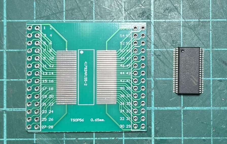
<p>I ordered some HT1621B chips and breakout boards from AliExpress. A few days later, I was ready to test.</p>

<p><a href="../assets/images/radioberry-ft80c-1/ht1621b-breakout.jpeg" target="_blank"><img src="../assets/images/radioberry-ft80c-1/ht1621b-breakout.jpeg" alt="HT1621B chip and breakout board" /></a></p>

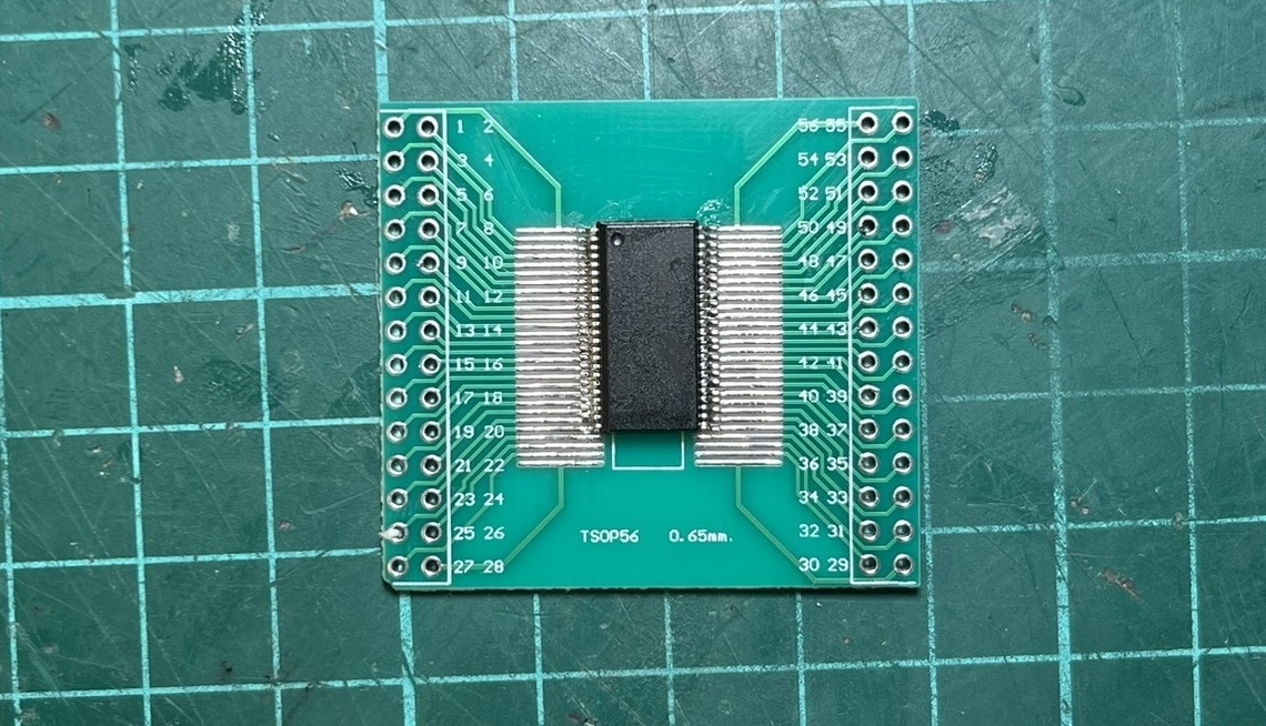
<p>Unfortunately, the breakout boards turned out to be 0.65mm pitch instead of the 0.635mm the chip expects. Close enough to work, but I had to carefully bend the pins on each chip to make them fit.</p>

<p><a href="../assets/images/radioberry-ft80c-1/ht1621b-breakout-soldered.jpeg" target="_blank"><img src="../assets/images/radioberry-ft80c-1/ht1621b-breakout-soldered.jpeg" alt="HT1621B chip sodered to the breakout board" /></a></p>

<p>The first test was simple: configure the HT1621B with the same parameters as the original controller and see if I got similar waveforms. I did.</p>

<p><a href="../assets/images/radioberry-ft80c-1/oscilloscope-ht1621b.png" target="_blank"><img src="../assets/images/radioberry-ft80c-1/oscilloscope-ht1621b.png" alt="HT1621B signal capture - matches original" /></a></p>

<p>The waveforms matched, but would it actually drive the display? I connected just COM0 and a single segment line to find out. When that first segment lit up on a display that hadn’t shown anything in days, I knew the approach would work.</p>

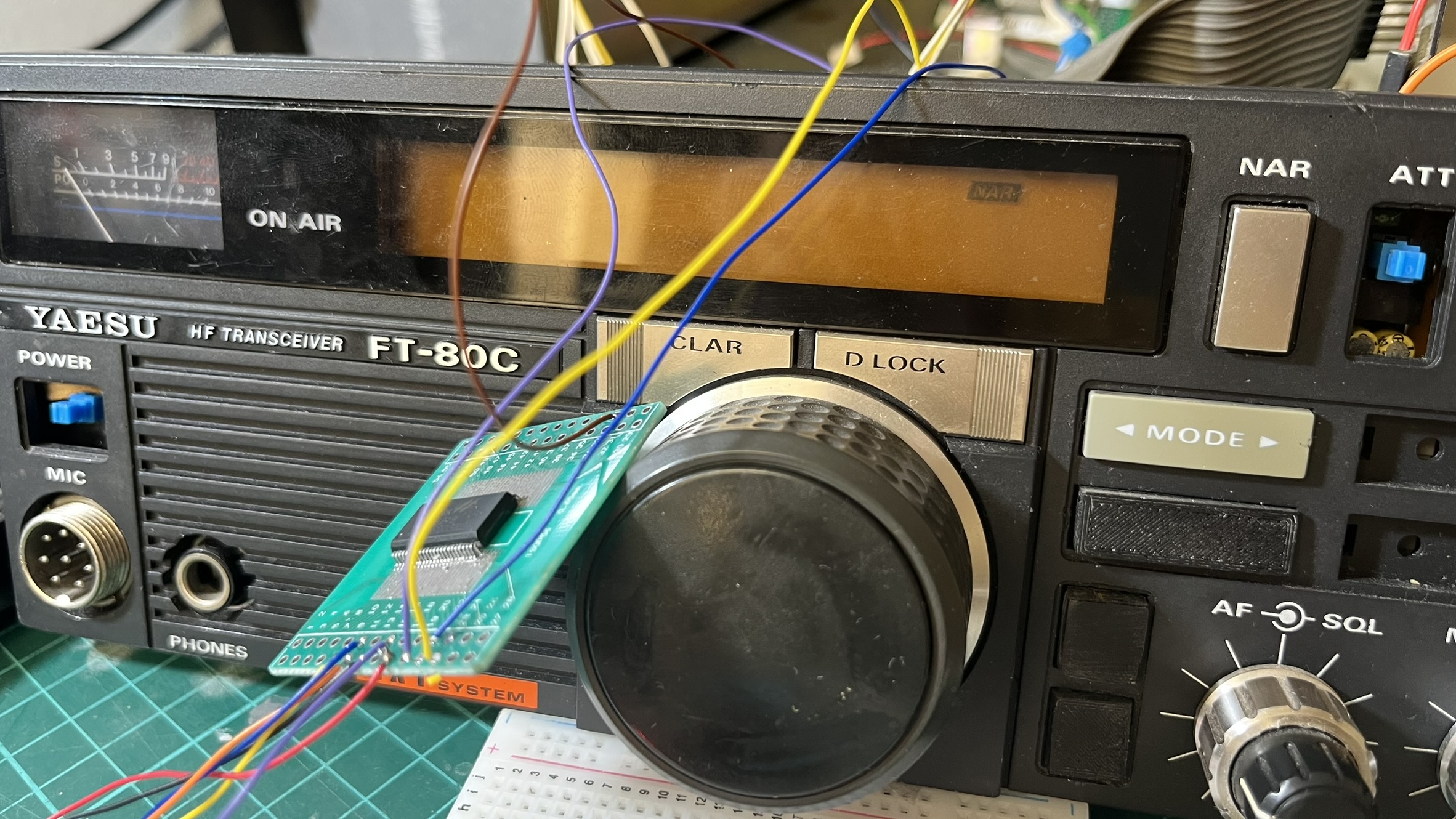
<p><a href="../assets/images/radioberry-ft80c-1/ft80c-lcd-cables-test.jpeg" target="_blank"><img src="../assets/images/radioberry-ft80c-1/ft80c-lcd-cables-test.jpeg" alt="First test with HT1621B - one segment lights up" /></a></p>

<h3 id="wiring-35-connections">Wiring 35 connections</h3>

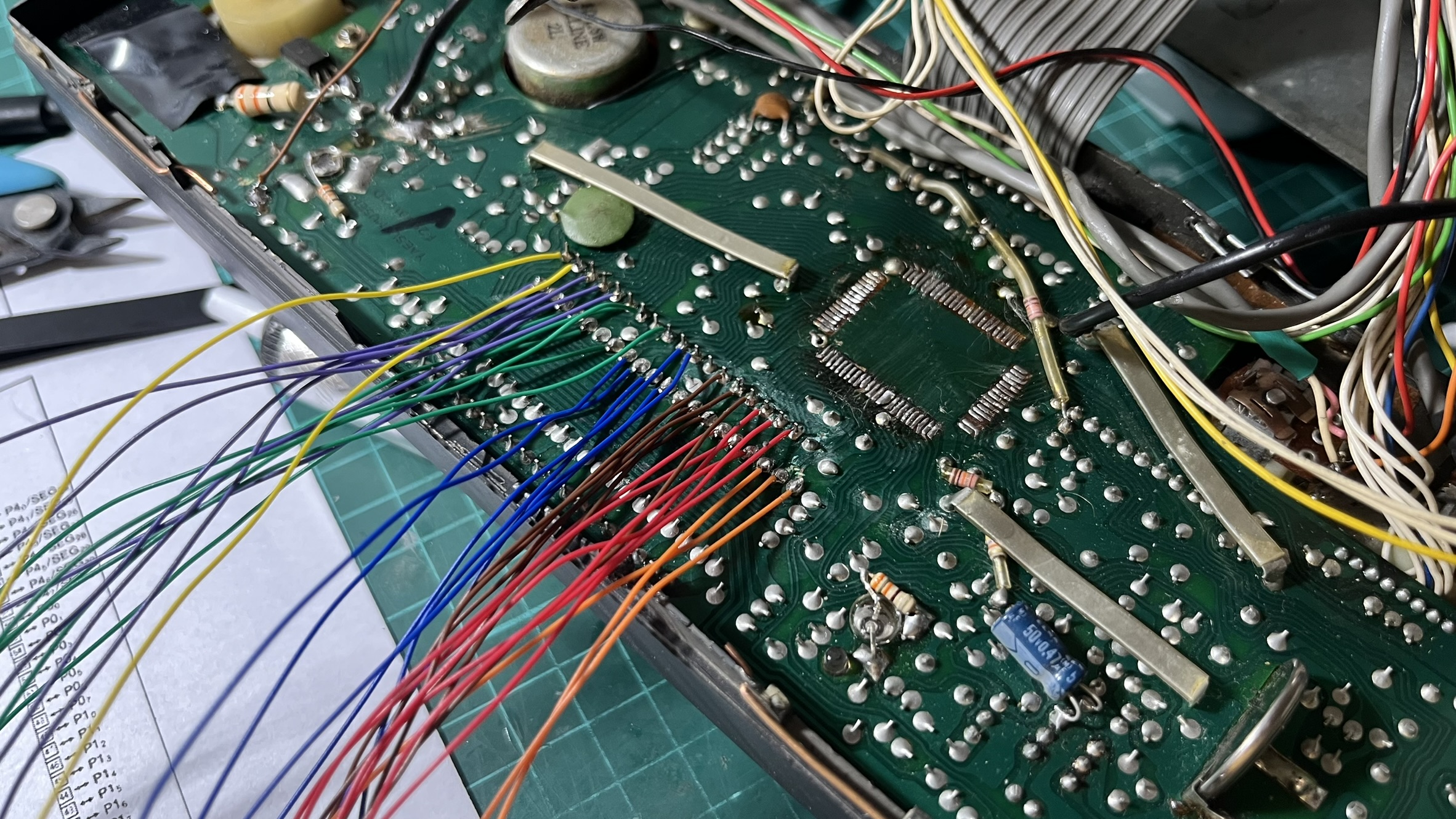
<p>The LCD has 32 segment lines plus 3 COM lines. I had to physically disconnect the M50932 from the display (isolating its outputs to prevent interference) and run 35 wires to the HT1621B.</p>

<p>To keep things organized, I used color-coded wires:</p>

<table>
  <thead>
    <tr>
      <th>Color</th>
      <th>Connections</th>
      <th>Count</th>
    </tr>
  </thead>
  <tbody>
    <tr>
      <td>Orange</td>
      <td>COM0, COM1, COM2</td>
      <td>3</td>
    </tr>
    <tr>
      <td>Red</td>
      <td>SEG0 - SEG5</td>
      <td>6</td>
    </tr>
    <tr>
      <td>Brown</td>
      <td>SEG6 - SEG11</td>
      <td>6</td>
    </tr>
    <tr>
      <td>Blue</td>
      <td>SEG12 - SEG17</td>
      <td>6</td>
    </tr>
    <tr>
      <td>Green</td>
      <td>SEG18 - SEG23</td>
      <td>6</td>
    </tr>
    <tr>
      <td>Purple</td>
      <td>SEG24 - SEG29</td>
      <td>6</td>
    </tr>
    <tr>
      <td>Yellow</td>
      <td>SEG30, SEG31</td>
      <td>2</td>
    </tr>
  </tbody>
</table>

<p><a href="../assets/images/radioberry-ft80c-1/lcd-wiring-colors.jpeg" target="_blank"><img src="../assets/images/radioberry-ft80c-1/lcd-wiring-colors.jpeg" alt="LCD wiring with color-coded cables" /></a></p>

<p>The soldering took a couple of hours. The connections on the display side are tiny surface-mount pads, and one wrong move could rip a trace.</p>

<h3 id="mapping-128-segments">Mapping 128 segments</h3>

<p>With the hardware connected, I still had to figure out which segment address controlled which part of the display. The HT1621B has 32 addresses, each controlling 4 bits (one per COM line), for a total of 128 possible segments.</p>

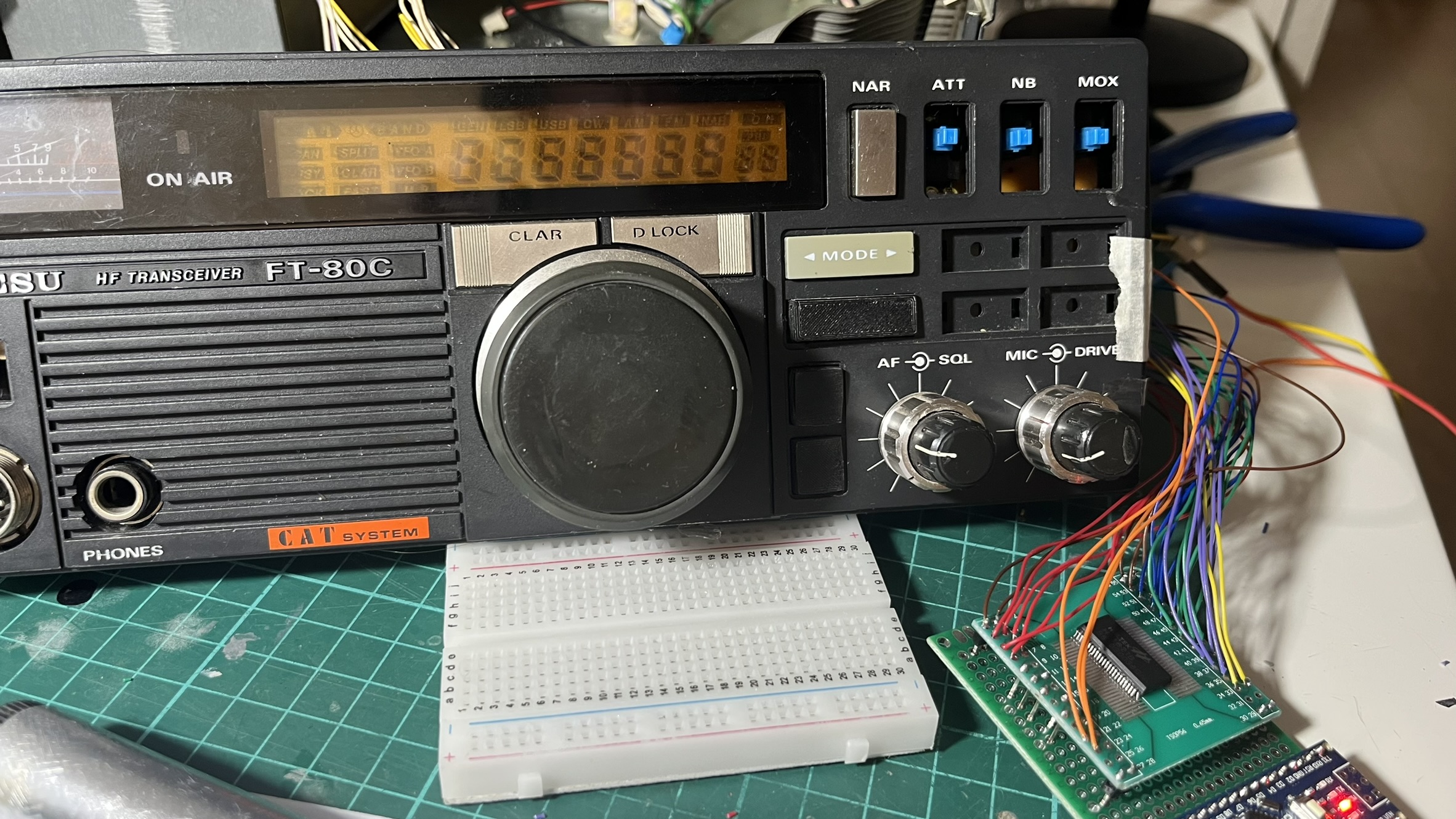
<p>I wrote a <a href="https://github.com/reynico/radioberry-setup/tree/main/lcd-controller-ft-80c/ht1621b_test">test program</a> that cycles through each segment one at a time, lighting it up for a couple of seconds while I noted down what it controlled. This mapping process took an entire afternoon. Address 7, bit 2 is segment A of digit 7. Address 29, bit 1 is the BUSY indicator. Address 21, bit 2 is the LSB mode indicator. And so on, 128 times.</p>

<p><a href="../assets/images/radioberry-ft80c-1/lcd-all-segments-test.jpeg" target="_blank"><img src="../assets/images/radioberry-ft80c-1/lcd-all-segments-test.jpeg" alt="LCD displaying my callsign LU3Arn" /></a></p>

<p>The result was a complete segment map that I encoded into a header file. Now I could display any frequency or indicator combination.</p>

<h3 id="connecting-to-pihpsdr">Connecting to piHPSDR</h3>

<p>The Arduino running the HT1621B code receives commands via serial from a Python bridge script on the Raspberry Pi. The bridge polls piHPSDR’s rigctl interface (port 19090) for frequency, mode, and S-meter readings, then forwards them to the Arduino using Kenwood CAT protocol.</p>

<pre><code>piHPSDR --&gt; lcd_bridge.py --&gt; Arduino --&gt; HT1621B --&gt; LCD Display
</code></pre>

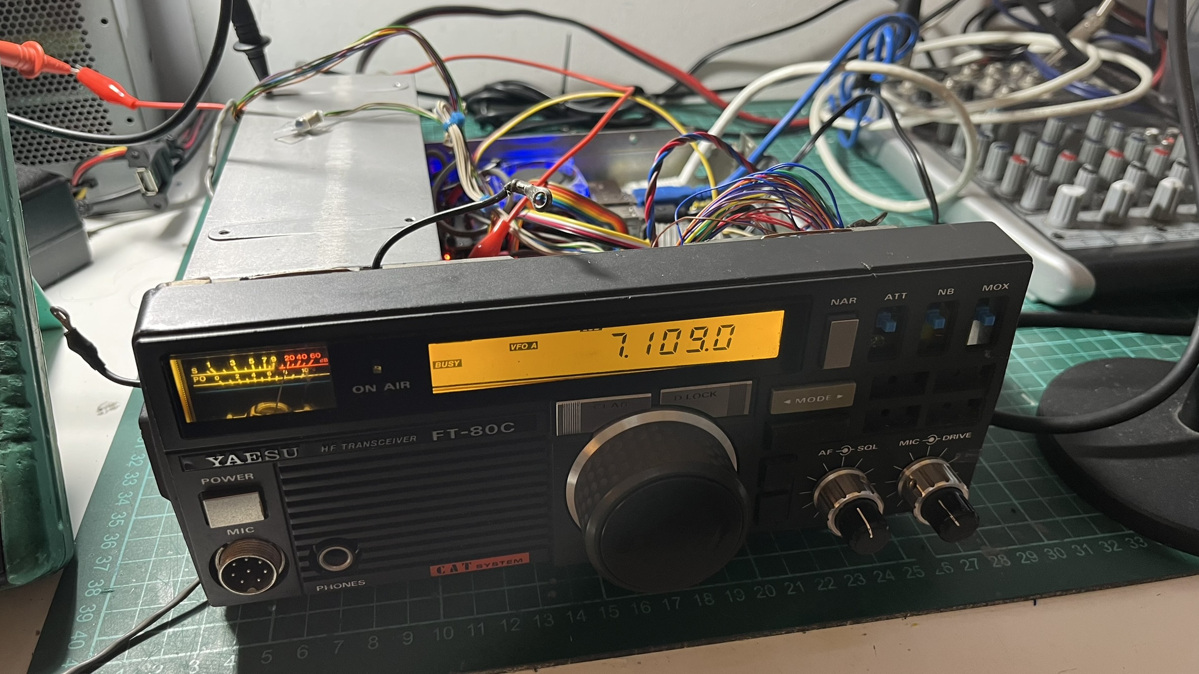
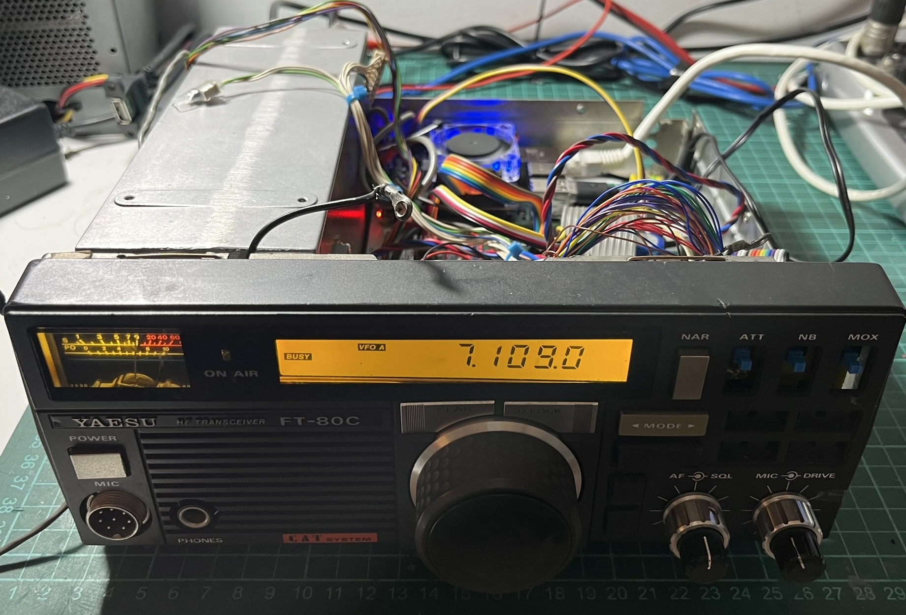
<p>The first time I saw the frequency update on the original LCD as I tuned in piHPSDR, I just stared at it for a while. After all that work mapping segments, seeing “7.109.0” appear on a display that hadn’t shown anything in years was genuinely exciting.</p>

<p><a href="../assets/images/radioberry-ft80c-1/lcd-frequency-working.jpeg" target="_blank"><img src="../assets/images/radioberry-ft80c-1/lcd-frequency-working.jpeg" alt="LCD showing frequency from piHPSDR" /></a></p>

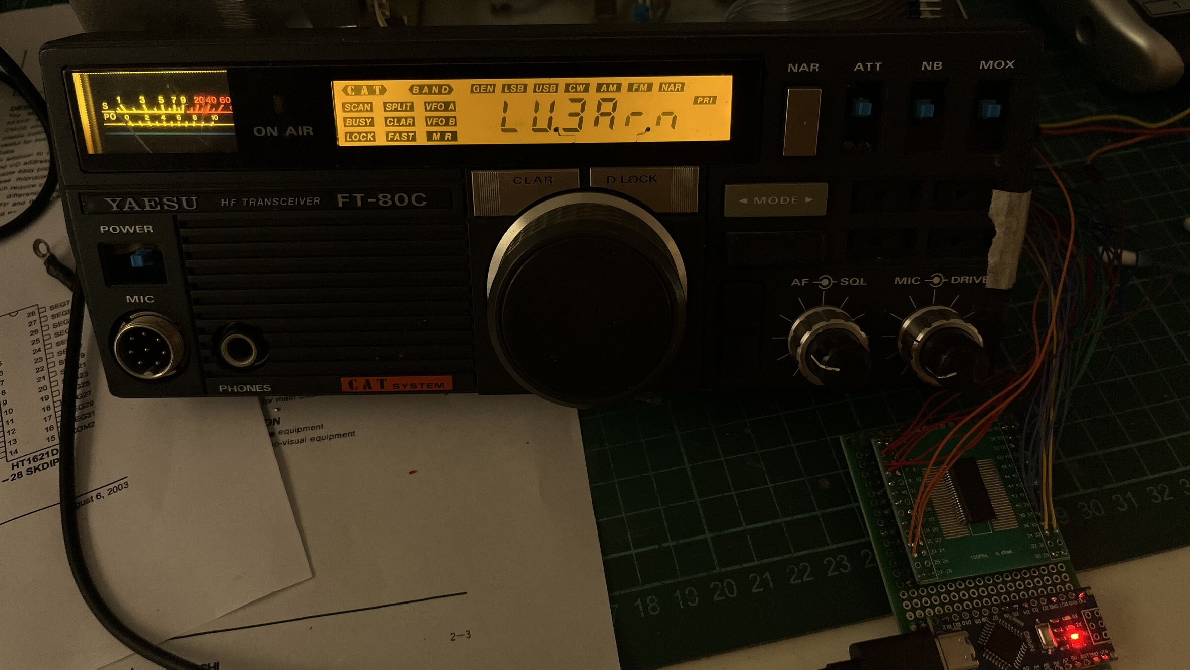
<p>I added a startup sequence that displays my callsign, “LU3Arn,” with all indicators lit. It’s a nice visual confirmation that the LCD controller is working before piHPSDR connects.</p>

<p><a href="../assets/images/radioberry-ft80c-1/lcd-callsign-lu3arn.jpeg" target="_blank"><img src="../assets/images/radioberry-ft80c-1/lcd-callsign-lu3arn.jpeg" alt="LCD showing callsign LU3Arn" /></a></p>

<h3 id="s-meter">S-meter</h3>

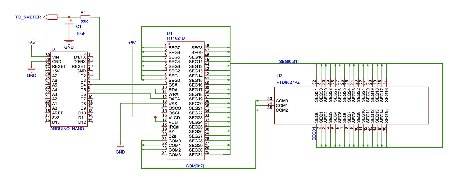
<p>The original FT-80C has an analog S-meter that I wanted to keep functional. The Arduino outputs a PWM signal on pin D3 based on the signal strength readings from piHPSDR. A simple RC low-pass filter (23k resistor + 10uF capacitor) converts the PWM to a smooth DC voltage that drives the meter movement. The time constant of about 230ms is slow enough to filter the PWM ripple but fast enough to follow signal changes.</p>

<p>The bridge script reads the S-meter value in dB from piHPSDR via CAT, scales it to 0-255, and sends it to the Arduino via the <code>SM</code> command.</p>

<p><a href="../assets/images/radioberry-ft80c-1/lcd-controller-schematic.png" target="_blank"><img src="../assets/images/radioberry-ft80c-1/lcd-controller-schematic.png" alt="LCD controller schematic" /></a></p>

<p><a href="../assets/images/radioberry-ft80c-1/ft80c-front-working.jpeg" target="_blank"><img src="../assets/images/radioberry-ft80c-1/ft80c-front-working.jpeg" alt="FT-80C front panel fully working" /></a></p>

<h2 id="power-supply-and-soft-shutdown">Power Supply and Soft Shutdown</h2>

<p>The last piece of the puzzle handles power regulation and graceful shutdown. The Raspberry Pi needs clean 5V, and the FT-80C doesn’t have an internal power supply - it runs from an external 13.8V source. I can’t just cut power abruptly without risking SD card corruption.</p>

<h3 id="voltage-regulation">Voltage regulation</h3>

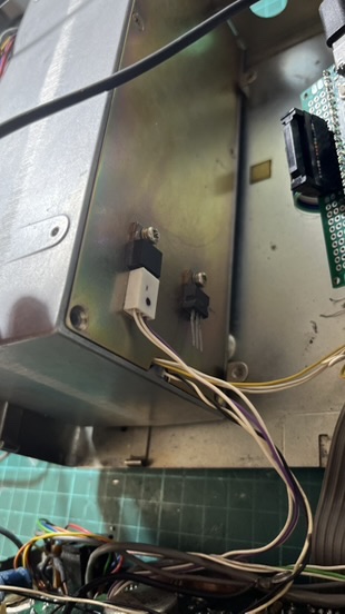
<p>I could have used a high-efficiency switching regulator, but I’m always paranoid about introducing noise into the system. On HF, switching noise can really mess with your signal - you’ll hear it as a constant buzzing or whine across the band. So I went with a less efficient but quieter approach: a linear regulator with a TIP3055 pass transistor mounted on the chassis as a heatsink. It wastes more power as heat, but I know for sure I won’t have electrical noise problems.</p>

<p><a href="../assets/images/radioberry-ft80c-1/voltage-regulator.jpeg" target="_blank"><img src="../assets/images/radioberry-ft80c-1/voltage-regulator.jpeg" alt="TIP3055 pass transistor mounted on chassis" /></a></p>

<h3 id="soft-shutdown-circuit">Soft shutdown circuit</h3>

<p>The shutdown circuit uses an OR gate to control a power relay. One input comes from a front panel switch (directly wired to GPIO4), the other from GPIO14 on the Raspberry Pi.</p>

<p>When you flip the power switch off:</p>
<ol>
  <li>GPIO4 goes low, triggering a shutdown script</li>
  <li>The script runs <code>poweroff</code> and waits</li>
  <li>When the Pi is fully off, GPIO14 goes low</li>
  <li>Both OR gate inputs are now low, opening the relay</li>
  <li>A large capacitor (4700uF) creates a slight delay before power cuts completely</li>
</ol>

<p>This gives the system about 10-15 seconds for a clean shutdown. No more corrupted SD cards from impatient power cycling.</p>

<p>At this point, I had all the boards working, but they were just sitting loose inside the chassis, held in place with tape and hope. Not exactly a permanent solution.</p>

<p><a href="../assets/images/radioberry-ft80c-1/ft80c-messy-progress.jpeg" target="_blank"><img src="../assets/images/radioberry-ft80c-1/ft80c-messy-progress.jpeg" alt="Boards loosely placed before the 3D printed mount" /></a></p>

<h3 id="mounting-everything">Mounting everything</h3>

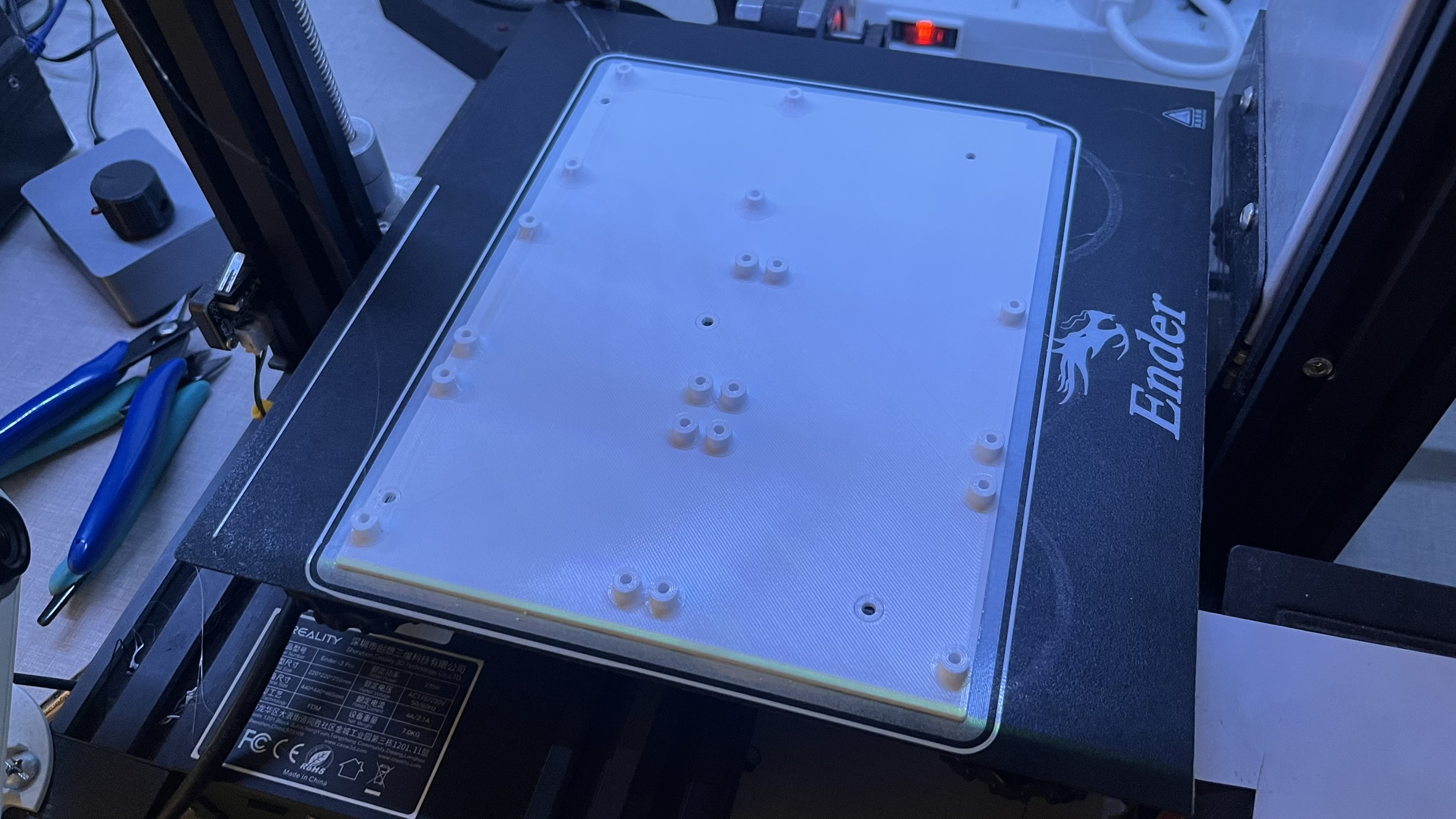
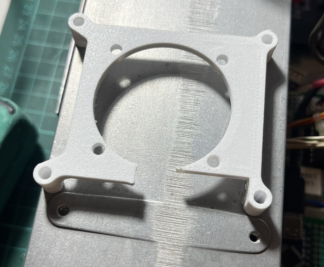
<p>I designed a 3D-printed board with the exact same dimensions and mounting holes as the original main board. This way it fits perfectly in the chassis using the existing standoffs. I added threaded inserts to mount the Raspberry Pi and all the control boards, making good use of the space left by the removed main board.</p>

<p><a href="../assets/images/radioberry-ft80c-1/3d-printed-mainboard-mount.jpeg" target="_blank"><img src="../assets/images/radioberry-ft80c-1/3d-printed-mainboard-mount.jpeg" alt="3D printed mounting board with threaded inserts" /></a></p>

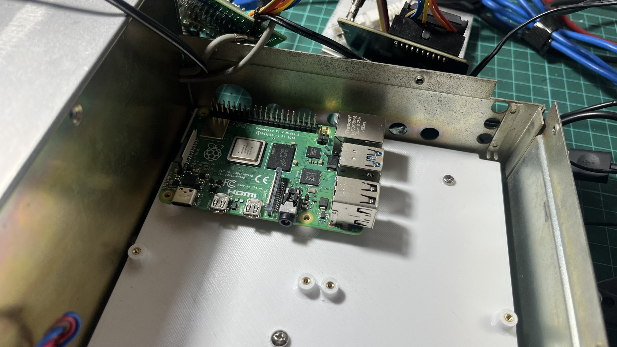
<p>The Raspberry Pi sits on this board with the RadioBerry HAT on top.</p>

<p><a href="../assets/images/radioberry-ft80c-1/rpi-mounted-detail.jpeg" target="_blank"><img src="../assets/images/radioberry-ft80c-1/rpi-mounted-detail.jpeg" alt="Raspberry Pi mounted on 3D printed bracket" /></a></p>

<p>The RadioBerry needs good airflow to keep the FPGA cool during TX. I printed a small bracket to hold a 40mm fan, with a cutout for the SMA connector that goes to the PA board.</p>

<p><a href="../assets/images/radioberry-ft80c-1/fan-mount-radioberry-connector.jpeg" target="_blank"><img src="../assets/images/radioberry-ft80c-1/fan-mount-radioberry-connector.jpeg" alt="Fan mount with connector cutout" /></a></p>

<h2 id="putting-it-all-together">Putting it all together</h2>

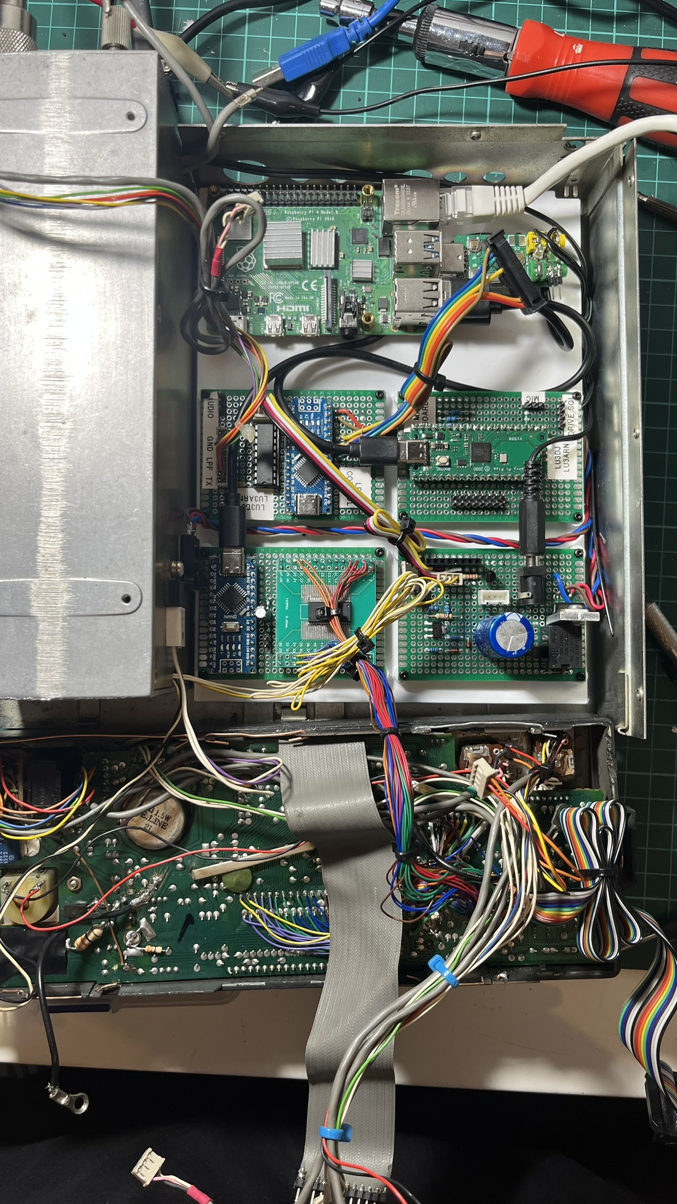
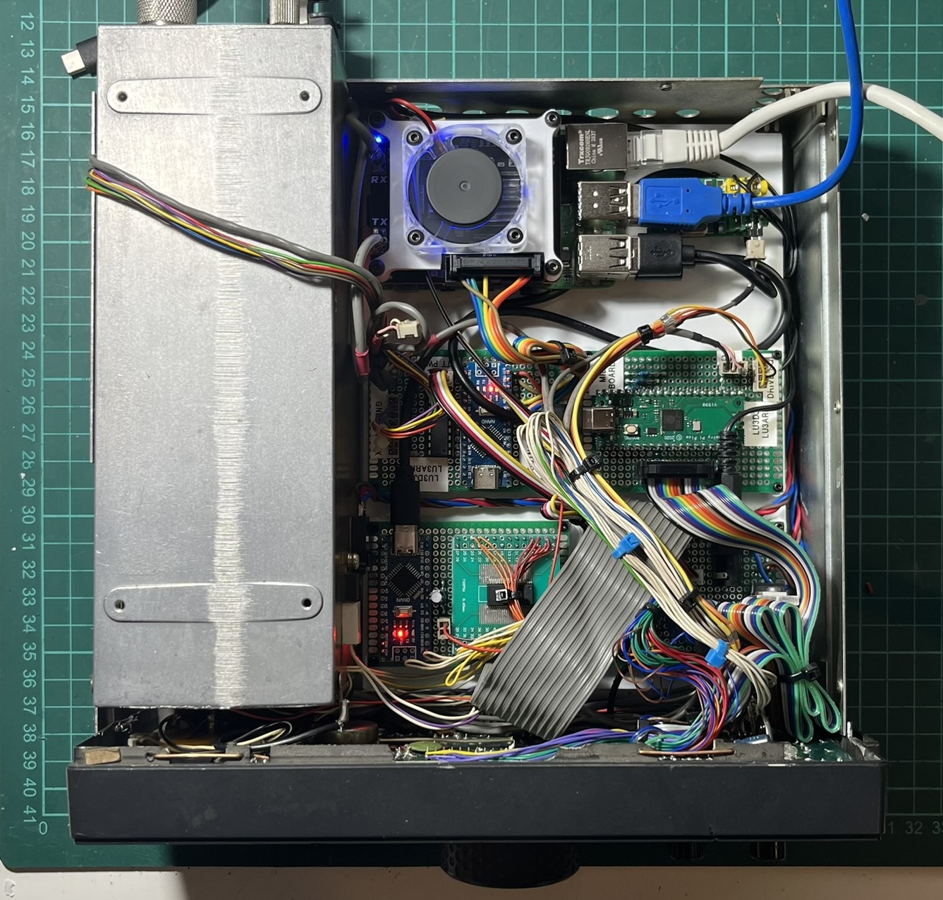
<p>With all the boards complete, I spent an afternoon routing cables and finding homes for everything inside the chassis. The four boards - LPF control, MIDI controller, LCD driver, and power supply - all mount on the 3D printed bracket.</p>

<p><a href="../assets/images/radioberry-ft80c-1/boards-mounted-on-3d-print.jpeg" target="_blank"><img src="../assets/images/radioberry-ft80c-1/boards-mounted-on-3d-print.jpeg" alt="All four boards mounted on the 3D printed bracket" /></a></p>

<p>It’s not the neatest installation - there are a lot of wires - but it all fits.</p>

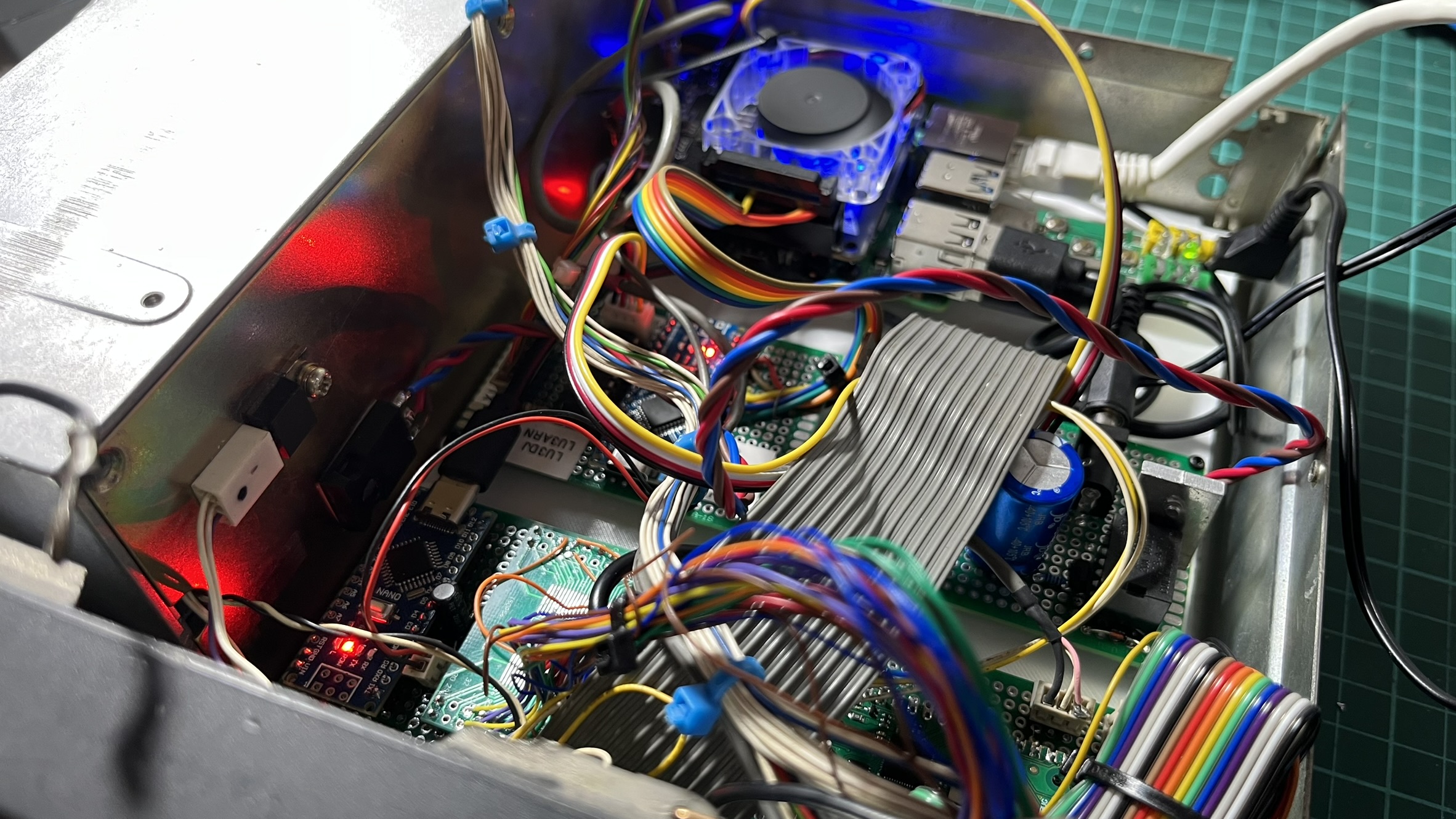
<p><a href="../assets/images/radioberry-ft80c-1/interior-with-leds.jpeg" target="_blank"><img src="../assets/images/radioberry-ft80c-1/interior-with-leds.jpeg" alt="Interior view with all components" /></a></p>

<p>The RadioBerry’s blue LED glows through the top vent, and you can see status LEDs from the Arduino boards if you look closely. The original cooling fan still works, keeping everything at reasonable temperatures.</p>

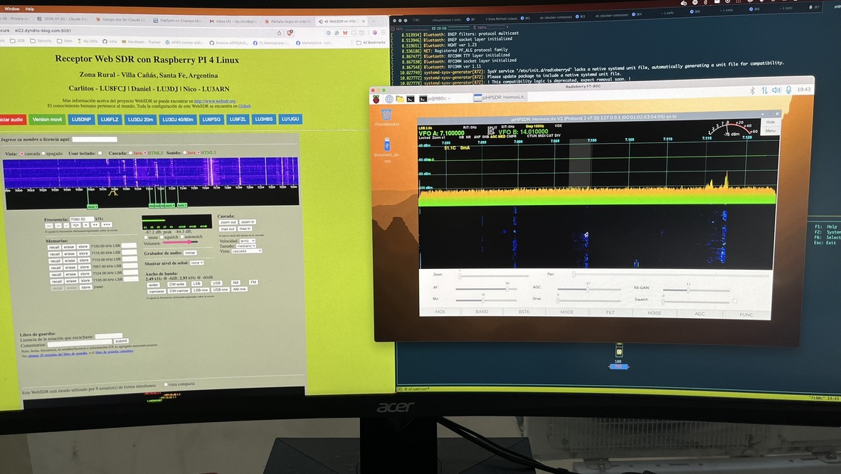
<p>Testing with piHPSDR confirmed that everything worked together: filter switching, PTT, all the buttons, the encoder, the LCD, and even the S-meter (which is driven by PWM from the LCD controller Arduino based on signal strength readings from piHPSDR).</p>

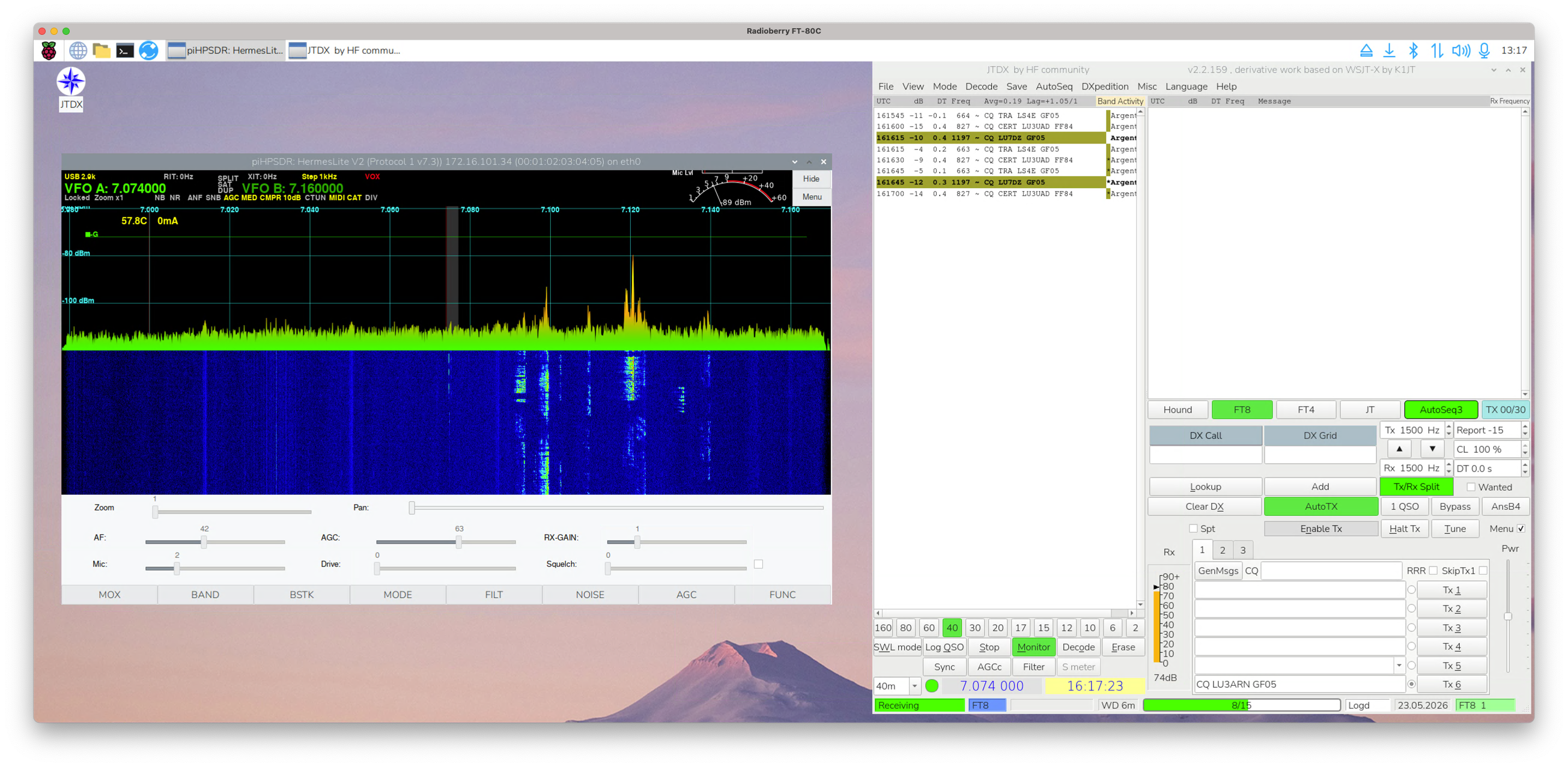
<p><a href="../assets/images/radioberry-ft80c-1/pihpsdr-websdr-test.jpeg" target="_blank"><img src="../assets/images/radioberry-ft80c-1/pihpsdr-websdr-test.jpeg" alt="Testing with piHPSDR" /></a></p>

<p>After several iterations of cable management, this is how it looks from above. All four boards are visible, cables are routed cleanly, and everything is secured in place.</p>

<p><a href="../assets/images/radioberry-ft80c-1/ft80c-top-view-final.jpeg" target="_blank"><img src="../assets/images/radioberry-ft80c-1/ft80c-top-view-final.jpeg" alt="Top view with all cables organized" /></a></p>

<p>The radio now boots up, displays our callsign while piHPSDR loads, then shows the current frequency and mode. All the original controls work. From the outside, it looks almost identical to how it did in 1988.</p>

<p><a href="../assets/images/radioberry-ft80c-1/ft80c-angle-working.jpeg" target="_blank"><img src="../assets/images/radioberry-ft80c-1/ft80c-angle-working.jpeg" alt="Another angle of the working radio" /></a></p>

<p>Tuned to 40 meters and receiving properly - the LCD showing frequency, the S-meter responding to signals.</p>

<p><a href="../assets/images/radioberry-ft80c-1/ft80c-tuning-working.jpeg" target="_blank"><img src="../assets/images/radioberry-ft80c-1/ft80c-tuning-working.jpeg" alt="FT-80C tuning and receiving" /></a></p>

<h2 id="3d-printed-front-panel-buttons">3D Printed Front Panel Buttons</h2>

<p>Since I repurposed the front panel buttons to work with piHPSDR and the RadioBerry, their original functions no longer matched what they actually did. I remapped them to functions that made more sense for this setup.</p>

<p>Fortunately, <a href="https://www.qrz.com/db/LU4BA">Matías - LU4BA</a> had shared <a href="https://www.thingiverse.com/thing:6796234">STL files for FT-80C buttons on Thingiverse</a>, which gave me a starting point. I went through several iterations trying to get them right.</p>

<p><a href="../assets/images/radioberry-ft80c-1/buttons_several_tests.jpeg" target="_blank"><img src="../assets/images/radioberry-ft80c-1/buttons_several_tests.jpeg" alt="Various button printing attempts" /></a></p>

<p>The main challenge was finding the right combination of material, layer height, and print orientation. Some came out too brittle, others didn’t fit the switches properly, and a few just looked wrong. After probably 8-10 test prints, I settled on a configuration that worked. Text were printed with 110% flow, and with a babystep-z of -0.1000.</p>

<p><a href="../assets/images/radioberry-ft80c-1/buttons_final_style.jpeg" target="_blank"><img src="../assets/images/radioberry-ft80c-1/buttons_final_style.jpeg" alt="Final button style" /></a></p>

<p>The final buttons are printed in PLA with 0.15mm layer height. I added text labels by pausing the print mid-layer and swapping to a different color filament for the lettering - a technique called filament swap.</p>

<p><a href="../assets/images/radioberry-ft80c-1/installed_buttons.png" target="_blank"><img src="../assets/images/radioberry-ft80c-1/installed_buttons.png" alt="Installed buttons on the front panel" /></a></p>

<p>They’re installed and functional now. I’m not 100% convinced about how they look - the originals had better texture and feel - but they work, and they’re definitely an improvement over missing buttons. The STL files I used are available in the <a href="https://github.com/reynico/radioberry-setup/tree/main/3d-printed-parts-ft-80c">GitHub repository</a>.</p>

<h2 id="the-7-lcd-display-challenge">The 7” LCD Display Challenge</h2>

<p>A few days after finishing the main build, the <a href="https://www.amazon.com/dp/B0D3QB7X4Z">Hosyond 7” touchscreen</a> I had ordered finally arrived. The plan was to mount it on top of the radio to run piHPSDR’s interface, giving me full control without needing an external monitor.</p>

<p><a href="../assets/images/radioberry-ft80c-1/lcd-screen-connected-pi4.jpeg" target="_blank"><img src="../assets/images/radioberry-ft80c-1/lcd-screen-connected-pi4.jpeg" alt="7&quot; LCD screen connected to Raspberry Pi 4" /></a></p>

<p>The screen worked perfectly when connected directly to the Raspberry Pi. The problem became apparent when I tried to figure out where to mount it: the included flex cable was way too short to route from the Pi inside the chassis to a display mounted on top of the radio.</p>

<p>I remembered I had bought some 30cm flex cable extensions a while back for another project. Perfect - or so I thought. I connected one extension, powered everything up, and the screen stayed dark. No backlight, no image, nothing.</p>

<p>After some head-scratching and multimeter probing, I figured out the issue: the flex cable extensions I had were straight-through cables (pin 1 to pin 1, pin 2 to pin 2, and so on), but the Hosyond display needed a crossover cable where the pins are reversed.</p>

<p>The solution was simple in theory but tedious in practice: I could chain two straight-through extensions together. The first one would flip the pins, the second one would flip them back, resulting in a crossover connection. This would give me a 60cm extension - more than enough length to route from the Pi to the top of the radio.</p>

<p><a href="../assets/images/radioberry-ft80c-1/lcd-screen-flex-build.jpeg" target="_blank"><img src="../assets/images/radioberry-ft80c-1/lcd-screen-flex-build.jpeg" alt="Flex cable extension being assembled" /></a></p>

<p>I carefully soldered the two 30cm extensions end-to-end, ensuring the connections were clean and the wiring neat. Flex cables are delicate, and a single cold-solder joint would mean redoing the whole thing.</p>

<p><a href="../assets/images/radioberry-ft80c-1/lcd-screen-test-flex.jpeg" target="_blank"><img src="../assets/images/radioberry-ft80c-1/lcd-screen-test-flex.jpeg" alt="Testing the custom flex cable extension" /></a></p>

<p>The first test was nerve-wracking. I connected everything, powered on, and the screen lit up immediately. Success.</p>

<p><a href="../assets/images/radioberry-ft80c-1/lcd-screen-working-pihpsdr.jpeg" target="_blank"><img src="../assets/images/radioberry-ft80c-1/lcd-screen-working-pihpsdr.jpeg" alt="7&quot; LCD showing piHPSDR interface" /></a></p>

<p>With piHPSDR running on the touchscreen, the radio finally feels complete. I can tune, switch modes, adjust settings, and view the waterfall - all without touching a keyboard or an external monitor.</p>

<p>Now I just needed a proper way to mount the screen on top of the radio. Just laying it flat would work, but it wouldn’t be comfortable to use. I wanted it angled, like a display you’d actually want to interact with.</p>

<p>I designed a simple mounting bracket in 3D with two legs that sit on top of the FT-80C chassis. The design holds the screen at a comfortable viewing angle - not too steep, not too flat. The bracket is essentially a box that the screen slides into, with cutouts for the cables and mounting holes to secure everything.</p>

<p><a href="../assets/images/radioberry-ft80c-1/lcd-box.jpg" target="_blank"><img src="../assets/images/radioberry-ft80c-1/lcd-box.jpg" alt="3D printed LCD mounting bracket" /></a></p>

<p>Once the print was done, I mounted the screen into the bracket. The fit was tight enough that it doesn’t move around, but I can still remove it if needed.</p>

<p><a href="../assets/images/radioberry-ft80c-1/lcd-box-mounted.jpg" target="_blank"><img src="../assets/images/radioberry-ft80c-1/lcd-box-mounted.jpg" alt="LCD mounted in bracket" /></a></p>

<p>The final result sits nicely on top of the radio. The angle makes it easy to see and use the touchscreen without hunching over. The flex cable routes cleanly from inside the chassis up to the display.</p>

<p><a href="../assets/images/radioberry-ft80c-1/lcd-box-mounted-final.jpg" target="_blank"><img src="../assets/images/radioberry-ft80c-1/lcd-box-mounted-final.jpg" alt="LCD bracket installed on radio" /></a></p>

<p>The <a href="https://github.com/reynico/radioberry-setup/tree/main/3d-printed-parts-ft-80c">STL files for the mounting bracket</a> are available in the GitHub repository if you want to print your own.</p>

<h2 id="frequency-calibration-from-hz-to-ppm">Frequency calibration: from Hz to PPM</h2>

<p>Once the radio was working, I noticed that the frequency wasn’t perfectly aligned. I had already seen this with the <a href="/radioberry-vertex-vx1700-1/">Vertex VX1700 build</a>, but back then we were mostly operating on 40 meters so it wasn’t a big deal. With the FT-80C I wanted to use multiple bands, and the issue became impossible to ignore.</p>

<p>piHPSDR has a <a href="https://apache-labs.com/public/storage/download_file/1756364890_1021_piHPSDR-Manual-3.pdf#page=43">Frequency Calibration</a> feature under Radio &gt; Frequency Calibration, but it works by adding a fixed Hz offset to all frequencies. The problem with this approach is that crystal oscillator errors are proportional to frequency - if I calibrated the offset for 7 MHz (40 meters), by the time I tuned to 28 MHz (10 meters), the error was four times larger and the frequency was visibly off.</p>

<p>I focused on 40 meters and 10 meters for calibration because, with my novice license, those are the only bands I’m allowed to transmit on. All testing was done into a dummy load to avoid transmitting on the air during the process.</p>

<p>To have a reliable reference signal, I used a second FT-80C (an original, unmodified one that I know is properly calibrated) transmitting into the dummy load at 7.060 MHz and 28.5 MHz. On the receiving side, I also verified the readings with an RTL-SDR v3 dongle that I had previously confirmed was frequency-accurate. So the calibration process involved three devices: the original FT-80C as a TX reference, the RTL-SDR as an independent RX reference, and the RadioBerry itself in both RX and TX modes. Not laboratory-grade equipment by any means, but reasonable enough for a home setup.</p>

<p><a href="../assets/images/radioberry-ft80c-1/40m-freq-cal-hz-rx-centered.png" target="_blank"><img src="../assets/images/radioberry-ft80c-1/40m-freq-cal-hz-rx-centered.png" alt="40m calibrated with Hz offset - centered" /></a></p>

<p>Here I had 40 meters calibrated with a fixed Hz offset, and the signal looked perfectly centered. But when I switched to 10 meters without changing the calibration value, this happened:</p>

<p><a href="../assets/images/radioberry-ft80c-1/10m-freq-cal-hz-rx-off.png" target="_blank"><img src="../assets/images/radioberry-ft80c-1/10m-freq-cal-hz-rx-off.png" alt="10m with the same Hz offset - frequency is off" /></a></p>

<p>The signal was clearly shifted. I could re-adjust the Hz offset to center it on 10 meters, but then 40 meters would be off again. You can’t win with a fixed offset.</p>

<p><a href="../assets/images/radioberry-ft80c-1/10m-freq-cal-hz-rx-centered.png" target="_blank"><img src="../assets/images/radioberry-ft80c-1/10m-freq-cal-hz-rx-centered.png" alt="10m re-calibrated with Hz offset - centered but 40m would be off" /></a></p>

<p>The correct way to handle this is with parts-per-million (PPM) calibration. Instead of adding a fixed number of Hz, you express the oscillator error as a ratio. A single PPM value scales proportionally with frequency - the correction at 28 MHz is automatically four times larger than at 7 MHz, matching the actual behavior of the oscillator error.</p>

<p>I <a href="https://github.com/g0orx/pihpsdr/issues/202">opened an issue</a> on the piHPSDR repository and then submitted a <a href="https://github.com/g0orx/pihpsdr/pull/205">pull request</a> implementing the change. The modification was small - about 22 lines added and 15 removed across 5 files. The core of it is a function that applies the PPM correction:</p>

<pre><code class="language-c">static inline long long freq_with_calibration(long long freq) {
  return freq + (long long)round((double)freq *
         calibration_ppm / 1e6);
}
</code></pre>

<p>The old code simply added <code>calibration</code> (in Hz) to every frequency. The new code multiplies the frequency by the PPM value divided by one million, producing a proportional correction that scales correctly across all bands.</p>

<p><a href="../assets/images/radioberry-ft80c-1/freq-cal-ppm-menu.png" target="_blank"><img src="../assets/images/radioberry-ft80c-1/freq-cal-ppm-menu.png" alt="PPM calibration menu in piHPSDR" /></a></p>

<p>With the PPM calibration in place, I set the value to -22.5 PPM and both bands were properly aligned with a single setting:</p>

<p><a href="../assets/images/radioberry-ft80c-1/40m-freq-cal-ppm-rx-centered.png" target="_blank"><img src="../assets/images/radioberry-ft80c-1/40m-freq-cal-ppm-rx-centered.png" alt="40m with PPM calibration - RX centered" /></a></p>

<p><a href="../assets/images/radioberry-ft80c-1/10m-freq-cal-ppm-rx-centered.png" target="_blank"><img src="../assets/images/radioberry-ft80c-1/10m-freq-cal-ppm-rx-centered.png" alt="10m with PPM calibration - RX centered" /></a></p>

<p>TX also confirmed proper alignment on both bands:</p>

<p><a href="../assets/images/radioberry-ft80c-1/40m-freq-cal-ppm-tx-centered.png" target="_blank"><img src="../assets/images/radioberry-ft80c-1/40m-freq-cal-ppm-tx-centered.png" alt="40m with PPM calibration - TX centered" /></a></p>

<p><a href="../assets/images/radioberry-ft80c-1/10m-freq-cal-ppm-tx-centered.png" target="_blank"><img src="../assets/images/radioberry-ft80c-1/10m-freq-cal-ppm-tx-centered.png" alt="10m with PPM calibration - TX centered" /></a></p>

<p>One PPM value, all bands calibrated. This is a small change, but it makes a real difference when you’re operating across the HF spectrum.</p>

<h2 id="remote-control-and-digital-modes">Remote control and digital modes</h2>

<p>At this point, the radio is fully functional and ready to use. All the major components are working: the PA stage, filter switching, front-panel controls, LCD display, and touchscreen interface. I’ve been using it on the air, and it performs well. I’d like to test the remoteness of the Radioberry module, such as the Hermes one. I compiled piHPSDR for my M1 Mac and successfully connected to the Radioberry module.</p>

<p><a href="../assets/images/radioberry-ft80c-1/pihpsdr-remote-macos.png" target="_blank"><img src="../assets/images/radioberry-ft80c-1/pihpsdr-remote-macos.png" alt="Remote control - PIHPSDR on a Mac" /></a></p>

<p>Still, I noticed that the TX/RX relay sometimes clicked, as if it were disconnecting the TX at a very high rate. At first, I thought the problem was that the readings from the Arduino controlling the LPF and TX relay were hitting a threshold, but that was not the case. Then I thought RF might be getting into the Arduino’s data lines, but I realized the problem was in the software itself. That was funny because the bug had existed all along. Still, when using it locally (as in, on the same machine for the server-client protocol), the time window between events is so small that the race condition doesn’t trigger. But even in a local network, a few microseconds of delay are painful. I ended up opening a pull request upstream to fix it: https://github.com/g0orx/pihpsdr/pull/207. After fixing it, I had a few successful QSOs using my Mac as the RadioBerry client, away from the radio shack.</p>

<p>I also wanted to test some digital modes. Although I am not a big fan of digital modes, I have found them useful for testing propagation. Firing up JTDX along with piHPSDR in a Remote Desktop session (so I can accommodate the windows on a higher-resolution screen) worked great. For PTT, I have used VOX in both programs; that way, I don’t need to mess around with RTS/DTR signals or hook up piHPSDR somehow. For the audio signals, I set two null sink modules (also known as virtual cables) so JTDX and piHPSDR can communicate bidirectionally.</p>

<p><a href="../assets/images/radioberry-ft80c-1/pihpsdr-jtdx.png" target="_blank"><img src="../assets/images/radioberry-ft80c-1/pihpsdr-jtdx.png" alt="JTDX" /></a></p>

<h2 id="lessons-learned">Lessons learned</h2>

<p>Compared to the VX1700 build, this one was significantly more complex. The VX1700 still had its original CPU board controlling the filters; I just had to interface with it. The FT-80C required rebuilding everything from scratch.</p>

<p>The modular approach (one board per function) was definitely the right call. When something didn’t work, I could test each board independently. The LCD controller alone went through three revisions before I got the segment mapping right.</p>

<p>The most satisfying moment was when I first tuned across 40 meters and heard CW signals coming through the speaker, with the original LCD showing the frequency and the S-meter bouncing. The radio that had been sitting there unused for years was alive again.</p>

<p><a href="https://github.com/reynico/radioberry-setup">All code, schematics, and documentation are available in the GitHub repository</a>. The LCD segment mapping alone might be useful if anyone else is trying to revive an FT-80C or FT-747GX.</p>]]></content><author><name>Nicolas Rey</name></author><category term="Radio" /><category term="Electronics" /><summary type="html"><![CDATA[Building a complete RadioBerry transceiver inside a Yaesu FT-80C]]></summary></entry><entry><title type="html">RadioBerry on a Vertex VX1700</title><link href="https://blog.nico.ninja/radioberry-vertex-vx1700-1/" rel="alternate" type="text/html" title="RadioBerry on a Vertex VX1700" /><published>2026-01-22T19:00:00+00:00</published><updated>2026-01-22T19:00:00+00:00</updated><id>https://blog.nico.ninja/radioberry-vertex-vx1700-1</id><content type="html" xml:base="https://blog.nico.ninja/radioberry-vertex-vx1700-1/"><![CDATA[<blockquote>
  <p>A note for the readers: This project is fully documented (from a technical perspective) in <a href="https://github.com/reynico/radioberry-setup">reynico/radioberry-setup</a></p>
</blockquote>

<p>Mid last year, my father introduced me to RadioBerry, an open-source FPGA-based Raspberry Pi Hat platform for HF SDR transceivers (0 to 30 MHz). The board uses an <a href="https://www.analog.com/en/products/ad9866.html">AD9866</a> modem chip and an Intel Cyclone FPGA (CL016 or CL025, depending on the manufacturer) for signal processing.</p>

<p>The board outputs a few milliwatts of RF power (100-150mW), enough to drive almost any commercial power amplifier. The recommended control software is <a href="https://github.com/g0orx/pihpsdr">PiHPSDR</a>, which packs a lot of features: PA control, low-pass filter board control for band selection, rigctl for Yaesu CAT systems, MIDI controller support for physical interfaces, and a very lengthy list of other capabilities.</p>

<p>Given that both of us were anxious to try it out, I ordered a complete kit on Aliexpress: 1GB Raspberry Pi 4, SD card, 7” touchscreen display, and the RadioBerry board itself. A few weeks later, the kit arrived, and we started playing with it.</p>

<p><img src="../assets/images/radioberry-vertex-1/kit.jpeg" alt="Kit from Aliexpress" /></p>

<p>The first thing I tried was tuning in some local AM broadcast stations to see if the thing could actually receive anything. I also made it transmit locally to check the modulation with an SDR dongle. I was surprised by the audio quality, given that I was using a cheap USB soundcard and a lavalier microphone for testing.</p>

<p><img src="../assets/images/radioberry-vertex-1/am-reception.jpg" alt="AM Broadcast reception" /></p>

<p>My dad mentioned he had a Vertex Standard (Yaesu) <a href="https://www.rigpix.com/protrx/vertexstandard_vx1700.htm">VX1700</a> HF SSB transceiver that could work for this project. The radio was missing its plastic front panel but otherwise functional. It pushed 100-120 watts of RF power, and the BPF board still worked. This seemed like the perfect foundation: a working amplifier stage with proper filtering, just waiting for a new interface.</p>

<p><img src="../assets/images/radioberry-vertex-1/vx1700.jpg" alt="Vertex VX1700" /></p>

<p>While my dad worked on the radio conversion—removing unneeded components, cleaning up, making RF adjustments—I started designing a 3D printed front panel that could house the 7” display, buttons, and knobs.</p>

<p><img src="../assets/images/radioberry-vertex-1/front-panel-bezel-1.png" alt="Front panel bezel" /></p>

<p>The panel ended up huge due to the screen size. A 5” display probably would have been better suited, but these were our first tests, so we went ahead with what we had. I used five KY-040 rotary encoders with push buttons, a 4x4 matrix keyboard, and a Raspberry Pi Pico RP2040 to emulate MIDI signals. The RP2040 connects to the Raspberry Pi 4 via USB.</p>

<p><img src="../assets/images/radioberry-vertex-1/bezel-mounting-1.jpeg" alt="Mounting encoders and keypad in bezel" /></p>

<p>From the operator’s perspective, it looked like this. The big hole down on the right was for the DIN microphone connector. That Arduino Nano in the back controls the BPF board.</p>

<p><img src="../assets/images/radioberry-vertex-1/front-panel-mounted.jpeg" alt="Front panel, mounted" /></p>

<p>And from behind, without the cover:</p>

<p><img src="../assets/images/radioberry-vertex-1/front-panel-from-back.jpeg" alt="Front panel, from back" /></p>

<p>After a few test prints and adjustments—mostly fitting issues, holes that were too small, bad tolerances, the usual 3D printing problems—this was the final result:</p>

<p><img src="../assets/images/radioberry-vertex-1/front-panel-bezel-2.jpeg" alt="Front panel RC1" /></p>

<p>Once the final front panel form was ready, we started putting everything together. The Raspberry Pi is now mounted on the radio, and the Arduino Nano controls the BPF board. The 3D-printed front panel houses the buttons, encoders, display, and RP2040. Between the front panel and the radio, there are only a few wires: microphone, PTT, the display’s flat cable, and the RP2040’s USB cable. You can also see a small speaker, a <a href="https://www.digikey.com/en/products/detail/diodes-incorporated/PAM8403DR-H/4033372">PAM8403</a> audio amplifier (I should be used a mono version), and a cheap USB audio interface. Initially, we used the USB audio interface’s speaker output, but it introduced too much noise. We ended up using the Raspberry Pi’s internal speaker jack instead. Now the USB audio card only handles microphone input.</p>

<p><img src="../assets/images/radioberry-vertex-1/vertex-populated-1.jpeg" alt="Vertex VX1700 populated" /></p>

<p>My dad operating the RadioBerry VX1700:</p>

<p><img src="../assets/images/radioberry-vertex-1/vx1700-working.png" alt="VX1700 working" /></p>

<p>Pushing almost 160W on SSB (1000W element slug):</p>

<p><img src="../assets/images/radioberry-vertex-1/bird-160w.jpeg" alt="Pushing 160w" /></p>

<h2 id="controlling-the-bpf-board">Controlling the BPF board</h2>

<p>The Vertex VX1700 BPF board has 7 built-in filters. Each filter line is enabled through a 12V relay. A Toshiba <a href="https://www.digikey.com/en/products/detail/toshiba-semiconductor-and-storage/TBD62783AFG-EL/5514113?">TD62783AFN</a> 8-channel driver board and a <a href="https://docs.rs-online.com/8825/0900766b8082ef51.pdf">TC4028BF</a> BCD-to-decimal encoder drive the relays. The VX1700’s CPU drives just three data lines.</p>

<p>Since this setup was already working, an Arduino Nano could handle both jobs: emulate an <a href="https://openhpsdr.org/alex.php">Alex filter board</a> (I2C address <code>0x21</code>) and control the truth table to drive the TC4028BF, and therefore the filter board.</p>

<table>
  <thead>
    <tr>
      <th><strong>Band</strong></th>
      <th><strong>Command (Alex board)</strong></th>
      <th><strong>C</strong></th>
      <th><strong>B</strong></th>
      <th><strong>A</strong></th>
      <th><strong>Selected filter</strong></th>
      <th><strong>Frequency</strong></th>
    </tr>
  </thead>
  <tbody>
    <tr>
      <td>160M</td>
      <td>1608</td>
      <td>0</td>
      <td>0</td>
      <td>1</td>
      <td>BPF1</td>
      <td>1.8 MHz</td>
    </tr>
    <tr>
      <td>80M</td>
      <td>1604</td>
      <td>0</td>
      <td>1</td>
      <td>0</td>
      <td>BPF2</td>
      <td>3.5 MHz</td>
    </tr>
    <tr>
      <td>60M</td>
      <td>1602</td>
      <td>0</td>
      <td>1</td>
      <td>1</td>
      <td>BPF3</td>
      <td>5.3 MHz</td>
    </tr>
    <tr>
      <td>40M</td>
      <td>802</td>
      <td>1</td>
      <td>0</td>
      <td>0</td>
      <td>BPF4</td>
      <td>7 MHz</td>
    </tr>
    <tr>
      <td>30M</td>
      <td>401</td>
      <td>1</td>
      <td>0</td>
      <td>1</td>
      <td>BPF5</td>
      <td>10.1 MHz</td>
    </tr>
    <tr>
      <td>20M</td>
      <td>101</td>
      <td>1</td>
      <td>1</td>
      <td>0</td>
      <td>BPF6</td>
      <td>14 MHz</td>
    </tr>
    <tr>
      <td>17M</td>
      <td>164</td>
      <td>1</td>
      <td>1</td>
      <td>0</td>
      <td>BPF6</td>
      <td>18.1 MHz</td>
    </tr>
    <tr>
      <td>15M</td>
      <td>264</td>
      <td>1</td>
      <td>1</td>
      <td>1</td>
      <td>BPF7</td>
      <td>21 MHz</td>
    </tr>
    <tr>
      <td>12M</td>
      <td>4</td>
      <td>1</td>
      <td>1</td>
      <td>1</td>
      <td>BPF7</td>
      <td>24.9 MHz</td>
    </tr>
    <tr>
      <td>10M</td>
      <td>4</td>
      <td>1</td>
      <td>1</td>
      <td>1</td>
      <td>BPF7</td>
      <td>28 MHz</td>
    </tr>
  </tbody>
</table>

<h2 id="controlling-the-front-panel">Controlling the front panel</h2>

<p>To control the front panel knobs and buttons, we used a Raspberry Pi Pico (RP2040), which offers plenty of timers and I/O pins. The front panel comprises five rotary encoders with buttons and a 4x4 keypad matrix.</p>

<p><img src="../assets/images/radioberry-vertex-1/front-panel-schematic.png" alt="Front panel schematics" /></p>

<p>The RP2040 acts as a MIDI controller emulator, reading the electrical signals and converting them to MIDI notes. PiHPSDR supports MIDI as a solution for interfacing in-app buttons with physical controls; you just need to map MIDI notes to actions.</p>

<h2 id="soft-power-off">Soft power off</h2>

<p>One problem with this implementation: the Raspberry Pi shouldn’t be powered off by simply cutting power. To avoid SD card wear, it’s better to power it off safely through the Raspbian menu or by calling a <code>poweroff</code> command.</p>

<p>The solution is an OR gate circuit. The first gate input comes from a front-panel switch that toggles 5V on or off. That same switch also signals a GPIO pin on the Raspberry Pi (<code>GPIO23</code>). The second gate input is signaled from the Raspberry Pi itself, from <code>GPIO14</code>. <code>GPIO14</code> goes low when the Raspberry Pi is powered off but still connected to the USB-C power supply. The output of the OR gate connects to an NPN transistor with a large capacitor (3300-4700µF), driving a power relay that shuts down power completely.</p>

<p>This way, if you power off the device from the front-panel switch, the Raspberry Pi is signaled to run <code>poweroff</code>. Once the Raspberry Pi is powered off, both inputs to the OR gate are low, shutting off power to the relay. The large capacitor hooked to the transistor’s base creates a slight delay in powering off the output, giving a few seconds of cooldown to keep things in the safe zone.</p>

<p><img src="../assets/images/radioberry-vertex-1/soft-shutdown-schematic.png" alt="Soft shutdown schematics" /></p>

<p>K1 controls the power supply for the Raspberry Pi.</p>

<p>A script runs on the Raspberry Pi in a loop to check whether <code>GPIO23</code> goes low. Note that if you don’t connect the circuit, you must add a pull-up wire to <code>GPIO23</code> to avoid shutting down the Raspberry Pi unexpectedly. You’ll need to install gpiod: <code>sudo apt install gpiod</code></p>

<pre><code class="language-bash">#!/bin/bash

CHIP=gpiochip0
PIN=23
HOLD_TIME_SECONDS=2

gpiomon --num-events=0 --rising-edge --falling-edge $CHIP $PIN | \
while read -r line; do
    if echo "$line" | grep -q "falling edge"; then
        START=$(date +%s.%N)
        while true; do
            VAL=$(gpioget $CHIP $PIN)
            NOW=$(date +%s.%N)
            ELAPSED=$(echo "$NOW - $START" | bc)
            if [ "$VAL" = "1" ]; then
                break
            fi
            if (( $(echo "$ELAPSED &gt;= $HOLD_TIME_SECONDS" | bc -l) )); then
                sudo poweroff
                exit 0
            fi
            sleep 0.05
        done
    fi
done

</code></pre>

<h2 id="conclusion-so-far">Conclusion (so far)</h2>

<p>This is an ongoing project, so you may find new additions over time. The RadioBerry works well and is highly customizable. However, the RadioBerry itself is just one part of a larger build.</p>

<p><a href="http://github.com/reynico/RadioBerry-setup">I’m documenting everything I’m learning with the RadioBerry in a GitHub repository</a>. This includes two radios: the Yaesu/Vertex VX1700 shown here and a Yaesu FT-80c I’m still building.</p>]]></content><author><name>Nicolas Rey</name></author><category term="Radio" /><category term="Electronics" /><summary type="html"><![CDATA[Our first steps into the RadioBerry]]></summary></entry><entry><title type="html">Leverage</title><link href="https://blog.nico.ninja/leverage/" rel="alternate" type="text/html" title="Leverage" /><published>2025-08-01T20:00:00+00:00</published><updated>2025-08-01T20:00:00+00:00</updated><id>https://blog.nico.ninja/leverage</id><content type="html" xml:base="https://blog.nico.ninja/leverage/"><![CDATA[<p>I first learned about the concept of a lever when I was a kid, working on a construction site. Despite being a hostile job (especially for a young person), having to carry construction debris with a wheelbarrow (a second-grade lever) or mix cement with a shovel (a third-grade lever) made things easier than carrying debris and cement by oneself.</p>

<p>Through the years, as I gained more context about the world I live in, I continued to learn about levers in various scenarios. Mundane things, such as riding a bike in the neighborhood, involve multiple levers, including brakes and pedals, as well as when using a hammer or a set of pliers (double first-grade levers) when building a tree house.</p>

<p>As I learned about economics, I learned about how one can leverage different investments to gain advantages over strategic resources and then achieve more juicy outputs (or dig your own grave).</p>

<p>Nowadays, the type of leverage I enjoy most involves working with people. People become powerful levers when you’re focused on building something. Since no one excels in every aspect or field needed, channeling specific problems to those with the right expertise multiplies your efforts exponentially. One hour of your time coordinating can generate dozens of hours of focused work.</p>

<p>However, not all coordination creates leverage—sometimes it does the opposite. I’ve learned this the hard way through countless meetings that felt more like time dividers than multipliers. The classic anti-pattern is the meeting without a clear purpose, where everyone sits around a table sharing updates that could have been an email.
How to avoid this anti-pattern? Conclude every meeting with clear action items for all participants. If people leave the meeting without action items on their plates, they probably didn’t need to be there.</p>

<p>Another leverage killer is micromanagement disguised as coordination. When you spend more time explaining how something should be done than it would take to do it yourself, you’ve created negative leverage. The same happens when you become a bottleneck—requiring your approval for every small decision, turning your team into people who wait rather than people who act.
How to avoid this? Set clear expectations about outcomes, not methods. And create explicit decision-making frameworks—define what requires your input and what doesn’t, then trust people to execute within those boundaries.</p>

<p>The key to effective human leverage lies in recognizing the right moments and the right people. I look for situations where someone else has deep expertise in an area I don’t, especially when that expertise can solve problems that would take me weeks to figure out. It’s also about timing—there’s a sweet spot where the problem is well-defined enough that I can communicate it clearly, but not so urgent that coordination time becomes a luxury I can’t afford.</p>

<p>The best leverage opportunities happen when you can provide context and direction that unlocks parallel work. Instead of doing five tasks sequentially yourself, you coordinate once and watch five people tackle them simultaneously, each bringing their specialized knowledge to bear on the specific challenge they’re best equipped to handle.</p>

<p>This shift from doing everything yourself to orchestrating outcomes through others represents a fundamental transformation in mindset. Leaders are always pursuing individuals who think like leaders, not followers. They want team members who can identify leverage points and act on them, rather than waiting to be told what to do. One book that taught me a lot about it is <a href="https://www.amazon.com/Turn-Ship-Around-Turning-Followers/dp/1591846404">‘Turn the Ship Around’ by David Marquet</a>. It’s the best book I’ve read on how great leaders multiply their impact by developing other leaders, rather than creating more followers.</p>

<p><img src="../assets/images/leverage-1/book.jpg" alt="Turn the Ship Around book" /></p>

<p>This also extends to peer relationships. When you invest time developing colleagues—mentoring, sharing resources, advocating for their growth—you’re creating leverage that benefits everyone. Their increased effectiveness multiplies your team’s capacity while demonstrating the leadership behavior that advances your own career.</p>

<p>The biggest leverage opportunity you’re probably missing is the one you’re too shy to ask for. That meeting with your CEO or CTO to discuss how to accelerate a project or solve a persistent problem? Schedule it. Most leaders got where they are because they understand leverage better than anyone—they want to see problems solved efficiently, not watch you struggle alone for weeks. One conversation with the right person can unlock resources, remove obstacles, or provide context that completely transforms your approach. The worst they can say is no, but more often than not, they’ll appreciate that you’re thinking strategically about multiplying impact rather than just grinding through tasks.</p>]]></content><author><name>Nicolas Rey</name></author><category term="Life" /><category term="Systems" /><summary type="html"><![CDATA[How to multiply your impact through people]]></summary></entry><entry><title type="html">What are you obsessed with?</title><link href="https://blog.nico.ninja/what-are-you-obsessed-with/" rel="alternate" type="text/html" title="What are you obsessed with?" /><published>2025-07-28T00:40:00+00:00</published><updated>2025-07-28T00:40:00+00:00</updated><id>https://blog.nico.ninja/what-are-you-obsessed-with</id><content type="html" xml:base="https://blog.nico.ninja/what-are-you-obsessed-with/"><![CDATA[<p>A few weeks ago, I was walking through <a href="https://en.wikipedia.org/wiki/Parque_del_Buen_Retiro,_Madrid">Parque de El Retiro in Madrid</a> with my friend <a href="https://manu.show/">Manu</a>. During our 1:30-hour walk, we discussed many interesting topics, one of which sparked my ideas: obsession.</p>

<p><img src="../assets/images/obsession/parque.jpg" alt="Parque de El Retiro" /></p>

<h3 id="what-are-you-obsessed-with">What are you obsessed with?</h3>

<p>Obsession is a great driver for accomplishing complex and intricate goals, but also for propelling us towards some obscure destinations. I always struggle to focus on the beneficial aspects of being obsessed with something, as it’s easy to get carried away. Once you’ve gone too far, the storm hits.</p>

<p>But how do you avoid being hit by the storm? Well, the most obvious answer is: don’t go out on a stormy day. But that’s not realistic, we need (and even we like) going out on stormy days. One thing that helps me avoid falling into the downward spiral of obsession is looking at myself in the mirror whenever I don’t feel at peace. Seeing my eyes, skin, and lips. The human body responds incredibly fast to stress (for the good and for the bad), you can quickly know you are exceeded, skin quality lows down, eyes become dry, you get chapped lips, you have bags under your eyes, you feel thirsty (dehydrated), caffeine doesn’t hit in a good way, instead, it gets you an anxiety boost. Everything is reflected in our bodies, in the things we see every day.</p>

<p>When I suspect I’m not doing well, I head to the mirror to analyze what I see. If any of the described symptoms are happening, I immediately go to my notebook. I write about how I feel, what I’m doing, and what might be driving me this way. It could be anything, from financial to family to work to something that happened that morning in the gym. However, most of the time, I’m dragging something out for a few days (or weeks/months), which requires further investigation. I usually start with these questions:</p>

<ul>
  <li>Why am I doing this?</li>
  <li>Do I want to do this?</li>
  <li>What am I expecting to happen from this thing?</li>
  <li>Is it worth it?</li>
  <li>How long will it take until I find myself in a better place? (assuming the thing that caused me this feeling is something that would put me in a better place). This could be <em>very</em> hard to answer, especially during the struggling period. I suggest leaving this for another moment.</li>
</ul>

<p>These questions can be challenging to answer, so you may need a few hours or a few days to complete them all. Once done, I usually find a sense of relief in my body, because I can articulate my mind and feelings in written words (handwritten works best), which means I have at least some clarity on what is making me feel this way. What I just did improves my overall clarity.</p>

<p>That is how I handle the bad side of being obsessed with something.</p>

<h3 id="but-what-about-the-good-side-of-obsession">But what about the good side of obsession?</h3>

<p>How does it feel? How is it managed?</p>

<p>Being genuinely obsessed with something really sparks joy; you feel energized, you go to bed thinking of it, and you wake up replenished, with your energy focused on working on it. Again, it could be anything, from financial to family, work, or even something related to your gym routine.</p>

<p>You drive through a tunnel of ideas and solutions, and you have complete clarity on what you are thinking, which becomes very obvious in the moment you want to share that idea with someone else. It is so crystal clear that you can just explain the most complicated thing in simple words, and the other person understands you fully.</p>

<p>I have a few current obsessions that I’m really enjoying. Here are a few, but not all:</p>

<ul>
  <li><strong>Isolated home automation:</strong> Home automation is one of my older obsessions. I started working on it in 2006, when I was 15 or 16 years old. I started by coding software that controlled a computer’s parallel port, allowing users to manage sensors and motors through a web server, either from their phone or another computer. I have never abandoned this obsession; instead, I have refined it over time, and now I run a Home Assistant server with several (over 30) custom-made ESPHome devices.</li>
</ul>

<p><img src="../assets/images/obsession/domoticacasera.png" alt="This was one of my first projects on home automation." /></p>

<blockquote>
  <p>This was one of my first projects on home automation.</p>
</blockquote>

<ul>
  <li><strong>Car restoration:</strong> In 2014, I purchased my first car, a 1991 Honda CRX, in decent condition, although not perfect. I embarked on a fantastic journey spanning over 10 years, exploring old, closed shops, meeting people online through forums, and making purchases from all over the world, ultimately ending up with a pile of OEM and new old stock car parts for my Honda, which I restored down to the last screw, painted, tuned and enjoyed up to today.</li>
</ul>

<p><img src="../assets/images/obsession/crx-parts.jpg" alt="Some OEM/NOS parts for Honda CRX. Probably under 3% of all the parts I accumulated during a decade." /></p>

<blockquote>
  <p>Some OEM/NOS parts for Honda CRX. Probably under 3% of all the parts I accumulated during a decade.</p>
</blockquote>

<ul>
  <li>
    <p><strong>Systems:</strong> Systems, in general, are something that sparks a lot of joy in me. I am always learning how to optimize my systems for habits, wellness, work, and overall wellbeing. For example, during 2024, I read fourteen books, divided into technical, psychological, and habits categories. I started consciously optimizing my systems not long ago. Still, I devote a significant amount of time and energy to this field every time I can. <a href="https://blog.nico.ninja/my-system/">You can read more about them here</a>.</p>
  </li>
  <li>
    <p><strong>Music:</strong> I have always enjoyed electronic music since I was a kid. My father introduced me to Giorgio Moroder and Kraftwerk records from the 70s, and that opened a tunnel of obsession in my mind. I currently scour the internet for records and old school electronic music sets. I am currently obsessed with <a href="https://soundcloud.com/search/sets?q=rave_on%20cattaneo">Hernán Cattaneo’s sets from the 1990s to the 2000s</a>. That mix of house and groovy sounds takes me right back in time, as if I were there.</p>
  </li>
</ul>

<p>Although there is a thin line between doing great with obsession and driving me crazy, I always find a lot of positive outcomes from them. I’ll never master obsession in the sense of not falling behind the storm, but I really prefer it as it is.</p>

<p>What are you obsessed with?</p>]]></content><author><name>Nicolas Rey</name></author><category term="Life" /><category term="Wellness" /><summary type="html"><![CDATA[The fine line between passion and madness—and why I choose to walk it]]></summary></entry><entry><title type="html">Testing a band-stop filter</title><link href="https://blog.nico.ninja/testing-a-band-stop-filter/" rel="alternate" type="text/html" title="Testing a band-stop filter" /><published>2025-07-09T22:50:00+00:00</published><updated>2025-07-09T22:50:00+00:00</updated><id>https://blog.nico.ninja/testing-a-band-stop-filter</id><content type="html" xml:base="https://blog.nico.ninja/testing-a-band-stop-filter/"><![CDATA[<p>Whenever I mount an SDR to listen in the 144-148 MHz band, I try to filter out the broadcast FM signals. This is due to the lack of proper filtering or channelization in the Software-Defined Radio receivers I use. The filter I use most is one described in the <a href="http://lna4all.blogspot.com/2015/10/diy-fm-trap-or-88-108-mhz-band-stop.html">LNA4ALL blog</a>. I even bought them a few LNAs and filters as well.</p>

<p><img src="../assets/images/band-stop-filter-1/complete.jpg" alt="Complete setup" /></p>

<p>The filter is extremely easy to build; you just need a small amount of copper wire, such as the type used in a telephone line pair, a small 30 x 10 mm PCB, and three ceramic capacitors.</p>

<p><img src="../assets/images/band-stop-filter-1/filter_detail.jpg" alt="Filter in detail" /></p>

<p>I even built a few of these filters while at my parents’ house, where my father has a NanoVNA vector analyzer, which makes filter adjustment easier. I don’t have one at home yet, and I wanted to tune the filter by adjusting the inductors, so I built an RF sweeper using what I had at hand: a HackRF and an RTL-SDR v3.</p>

<p><img src="../assets/images/band-stop-filter-1/Figure_1_filter_comparison.png" alt="No filter vs filter comparison" /></p>

<p>The theory is simple: the HackRF would transmit an IQ sample at a given frequency, with a given sample rate and power. The RTL-SDR v3 would tune in the same frequency as the HackRF and take a few samples of the signal magnitude. Then both devices would move upwards in frequency.</p>

<p>After a few tests to ensure everything was working as expected, I attempted to improve the filtering capabilities, but I failed. I simply failed. The best cutting frequency I got was with the untouched filter specs. Opening up the 126nH inductor winding shifts the filter’s cut frequency downward.</p>

<p><img src="../assets/images/band-stop-filter-1/filter_coil_open.jpg" alt="Coil winding open" /></p>

<p><img src="../assets/images/band-stop-filter-1/Figure_2_filter_open_coil.png" alt="Coil winding open results" /></p>

<p>This little project turned out way better than expected. I didn’t manage to improve the filter, as it turns out the LNA4ALL guys knew what they were doing from the start. However, I now have a simple RF sweeper that works quite well for basic measurements. Sometimes, the tools you build yourself end up being more useful than the original project for which you built them. Also, I learned a lot during this journey.</p>

<p>Check <a href="https://github.com/reynico/rf-response-sweep">my repository at GitHub</a> for more information, code, and example measurements.</p>

<p>Ah, oh, I almost forgot! Yes, the <a href="https://sdr.nico.ninja:8443/">OpenwebRX+ receiver</a> now has a lower noise level, and stations emboss a bit more, you can compare it with the <a href="https://blog.nico.ninja/dual-band-openwebrx/">initial setup I made in December</a>:</p>

<p><img src="../assets/images/band-stop-filter-1/openwebrx_filtered.png" alt="Current noise level and signals" /></p>]]></content><author><name>Nicolas Rey</name></author><category term="Radio" /><category term="Electronics" /><summary type="html"><![CDATA[Automated RF frequency response measurement using HackRF and RTL-SDR]]></summary></entry><entry><title type="html">Building a Smarter Weekly Meal Planner with AI</title><link href="https://blog.nico.ninja/ai-weekly-meals-planner/" rel="alternate" type="text/html" title="Building a Smarter Weekly Meal Planner with AI" /><published>2025-04-28T00:00:00+00:00</published><updated>2025-04-28T00:00:00+00:00</updated><id>https://blog.nico.ninja/ai-weekly-meals-planner</id><content type="html" xml:base="https://blog.nico.ninja/ai-weekly-meals-planner/"><![CDATA[<p>The FOMO about AI caught me. While I use Chat GPT and Claude for some of my daily tasks (even searching for things), I missed a good opportunity by not boarding the AI Agent development wave. Intuitively, my first question was: What should I do with my AI Agent?</p>

<ul>
  <li><a href="#a-brief-context">A brief context</a></li>
  <li><a href="#honey-what-do-you-want-to-eat-this-week">Honey, what do you want to eat this week?</a>
    <ul>
      <li><a href="#iteration-1-a-simple-approach">Iteration #1: A simple approach</a></li>
      <li><a href="#iteration-2-repeated-dishes">Iteration #2: Repeated dishes</a></li>
      <li><a href="#iteration-3-seasonal-dishes">Iteration #3: Seasonal dishes</a></li>
      <li><a href="#iteration-4-refining-the-embeddings-part-1">Iteration #4: Refining the embeddings (part 1)</a></li>
      <li><a href="#iteration-5-testing-the-embeddings-part-1">Iteration #5: Testing the embeddings (part 1)</a></li>
      <li><a href="#iteration-6-refining-the-embeddings-part-2">Iteration #6: Refining the embeddings (part 2)</a></li>
      <li><a href="#iteration-7-testing-the-embeddings-part-2">Iteration #7: Testing the embeddings (part 2)</a></li>
      <li><a href="#iteration-8-prompts-are-too-large">Iteration #8: Prompts are too large</a></li>
      <li><a href="#iteration-9-improving-the-penalty-filter">Iteration #9: Improving the penalty filter</a></li>
      <li><a href="#iteration-10-moving-to-openais-o4-mini">Iteration #10: Moving to OpenAI’s o4-mini</a></li>
      <li><a href="#iteration-11-external-embedding-models-part-1">Iteration #11: External embedding models (part 1)</a></li>
      <li><a href="#iteration-12-testing-the-embeddings-part-3">Iteration #12: Testing the embeddings (part 3)</a></li>
      <li><a href="#iteration-13-refining-the-embeddings-part-3">Iteration #13: Refining the embeddings (part 3)</a></li>
      <li><a href="#iteration-14-external-embedding-models-part-2">Iteration #14: External embedding models (part 2)</a></li>
      <li><a href="#iteration-15-the-dish-replacement-bug">Iteration #15: The dish replacement bug</a></li>
      <li><a href="#iteration-16-scored-dishes">Iteration #16: Scored dishes</a></li>
    </ul>
  </li>
  <li><a href="#conclusion">Conclusion</a></li>
</ul>

<h1 id="a-brief-context">A brief context</h1>

<p>Almost two years ago, we hired a chef who is in charge of our weekly meals, including lunch, dinner, and some extras, such as grocery shopping (fruits, vegetables, etc.). The modus operandi is straightforward: We have a WhatsApp group where we share with the chef what we want to eat this week, and sometimes, the chef does that job for us, prepping a potential list of meals. Then, we make some adjustments to that list. Since then, I have stored the whole chat history with all the dishes we ordered and were offered. One of the things we struggle with sometimes is answering the following question.</p>

<h1 id="honey-what-do-you-want-to-eat-this-week">Honey, what do you want to eat this week?</h1>

<p>While it may seem a pretty straightforward question, it requires a lot of work and coordination, given that we usually go out for dinner or are travelling. I found a good use case for my soon-to-be-born AI agent: an agent to build the weekly meals list so we don’t need to think about that anymore, feeding it with our two-year WhatsApp chat contents.</p>

<h2 id="iteration-1-a-simple-approach">Iteration #1: A simple approach</h2>

<p>The first iteration used Deepseek’s AI engine through the <a href="https://github.com/openai/openai-python">OpenAI Python library</a>. <a href="https://api-docs.deepseek.com/">Deepseek</a> is fully compatible with the OpenAI endpoints, so it was a good idea even if I wanted to move to another AI engine.</p>

<p>With this first iteration, I just tried to load all the exported WhatsApp chats into an SQLite3 database by reading the file line by line. What a bad idea. While the import worked, the resultant embedding model was disastrous at best. While the WhatsApp group remains very silent most of the time, there is a lot of noise hanging around, like questions about which brand of olive oil to buy or if we want Greek yogurt or a normal one. Since I had no idea what I was doing, I built a relevant context getter from those embeddings. Then, the <code>create_new_menu</code> method will use the embeddings to craft a new menu for the week.</p>

<pre><code class="language-python">async def create_new_menu(chat_id: int) -&gt; str:
    try:
        historical_context = get_relevant_context("generar menú semanal")

        system_prompt = f"""
        Eres un asistente que genera menús semanales para nuestro cocinero.

        Contexto importante:
        - El menú es para preparación semanal, en lo posible no deben repetirse con semanas anteriores cercanas
        - Evitar alto contenido de gluten y lácteos (intolerancias)
        - Puede incluir algunos platos con gluten/lácteos, pero deben ser minoría
        - Siempre incluir los items de 'Y te pedimos' exactamente como se especifica
        - El mensaje DEBE comenzar con "Hola! Te pasamos el menú para esta semana:"
        - El mensaje DEBE terminar con "Gracias!"
        - No incluir ninguna otra explicación, comentario o texto adicional
        - No incluir si el plato tiene o no tiene gluten, o si tiene o no tiene lacteos.

        Preferencias históricas:
        {historical_context}

        Requisitos estrictos:
        - Estructura clara con números y asteriscos para los platos
        - 10 platos principales variados
        - Cada plato debe ser completo (proteína + acompañamiento)
        - Incluir sección 'Y te pedimos' con los items exactos requeridos

        Formato obligatorio:

        1. Plato 1
        2. Plato 2
        ...
        3.  Plato 10

        Y te pedimos
        4. pan de masa madre
        5. maple de huevos de granja
        6. 3-4 paltas
        7. bananas
        8. yogur griego
        9. 3 manzanas
        10. 2 duraznos
        ...
        11. [otros items de tu lista]

        """

        user_prompt = """
        Por favor genera un menú semanal completo con:
        - 10 platos principales variados
        - Que sean aptos para preparación semanal
        - Máximo 2 platos con gluten/lácteos
        - Incluye la sección 'Y te pedimos' exactamente como se especificó
        """

        response = deepseek_client.chat.completions.create(
            model="deepseek-chat",
            messages=[
                {"role": "system", "content": system_prompt},
                {"role": "user", "content": user_prompt}
            ],
            temperature=TEMPERATURE,
            top_p=TOP_P,
            max_tokens=MAX_TOKENS
        )

        menu_text = response.choices[0].message.content

</code></pre>

<p>The results were far from ideal, but I was amazed by the power of the AI. This was the first working result:</p>

<pre><code>🍽️ Tu menú semanal 🍽️

Hola \! Te pasamos el menú para esta semana:

1\. Curry de garbanzos con espinacas y leche de coco \+ arroz basmati
2\. Salmón al horno con costra de almendras \+ puré de coliflor
3\. Wok de tofu y vegetales \(pimiento, zanahoria, brócoli\) \+ fideos de arroz
4\. Milanesas de berenjena \(sin gluten\) \+ ensalada de rúcula y cherry
5\. Guiso de lentejas con zapallo y chorizo colorado \+ quinoa
6\. Pollo al limón con romero \+ papas rústicas al horno
7\. Tartar de palta y mango \+ crackers de semillas \(1 plato con gluten\)
8\. Estofado de ternera con hongos \+ puré de boniato
9\. Ensalada de quinoa con tomate, pepino y aceitunas \+ huevo pochado
10\. Pizza de harina de garbanzos \(1 plato con lácteos\) \+ mix de verdes

Y te pedimos
* pan de masa madre
* maple de huevos de granja
* 3\-4 paltas
* bananas
* 1kg de tomates cherry
* 1 frasco de almendras
* 1 paquete de quinoa
* 1 leche de coco

Gracias\!
</code></pre>

<h2 id="iteration-2-repeated-dishes">Iteration #2: Repeated dishes</h2>

<p>After playing for a few minutes with the bot, I found that it was repeating most of the dishes all the time. Sometimes they were repeated literally, and sometimes in different forms, example:</p>

<pre><code>First round:
2\. Salmón al horno con costra de almendras \+ puré de coliflor y espinacas

Second round:
2\. Salmón al horno con costra de almendras \+ puré de coliflor

Third round:
2\. Salmón al horno con costra de almendras \+ puré de coliflor

Fourth round:
2. Salmón al horno con puré de coliflor y espárragos
</code></pre>

<p>So I started to refine the prompt, asking the engine to generate completely new weekly meals for today and to avoid recently offered dishes (I was storing the generated dishes in the SQLite database).</p>

<p><img src="/assets/files/ai-weekly-meals-planner-1/image.png" alt="Prompt refinery take one" /></p>

<p>That improved the generation significantly, at least the same-index dishes were not repeated.</p>

<pre><code>first round:
2. Wok de ternera con brócoli, zanahoria y castañas de cajú + fideos de arroz

second round:
2. Tartar de atún con palta y crackers de arroz

third round:
2. Pollo al curry verde con leche de coco y arroz jazmín

fourth round:
2. Pechuga de pollo rellena de espinacas y almendras + puré de boniato
</code></pre>

<h2 id="iteration-3-seasonal-dishes">Iteration #3: Seasonal dishes</h2>

<p>After researching the recommended dishes, I discovered some ingredients were unavailable this season. So I thought of adding more context to the prompt, by asking the agent to mind about the season we are in:</p>

<pre><code>        today = datetime.datetime.now()
        current_month = today.month
        if 3 &lt;= current_month &lt;= 5:
            season = "otoño"
        elif 6 &lt;= current_month &lt;= 8:
            season = "invierno"
        elif 9 &lt;= current_month &lt;= 11:
            season = "primavera"
        else:
            season = "verano"

        system_prompt = f"""
...
- Estamos en {season}, considera ingredientes de temporada.
- Vivimos en Argentina. Es importante que elijas alimentos que se consigan aquí.
</code></pre>

<p>That new input improved the ingredient selection significantly. Now, the agent recommends Mangoes and avoids Pears in the summer.</p>

<h2 id="iteration-4-refining-the-embeddings-part-1">Iteration #4: Refining the embeddings (part 1)</h2>

<p>At this point, I briefly paused to think more about the embeddings, and I had an A-ha moment when I discovered that the <code>get_relevant_context()</code> method was returning a lot of nonsensical data, as in, data that was utterly useless as input to generate a new menu. While sometimes the context contained a few dishes, most of the time, there were non-contextual messages about bills or discussions about other things from the WhatsApp group. The first refining loop was to improve the message match pattern when creating the embeddings in the database:</p>

<p><img src="/assets/files/ai-weekly-meals-planner-1/image%201.png" alt="Fixing the regexes" /></p>

<p>Now the menu was getting way more consistent.</p>

<pre><code>Hola! Te pasamos el menú para esta semana:

1. Merluza al horno con romero y puré de zapallo anco
2. Pollo al horno con piel crocante y ensalada de radicheta, pera y nueces
3. Wok de ternera con brócoli, zanahoria y jengibre + arroz yamaní
4. Budín de calabaza con huevo y semillas de amapola + mix de hojas verdes
5. Suprema de pollo rellena de espinaca y pasas de uva + puré de manzana y zanahoria
6. Ensalada tibia de garbanzos, berenjena asada, tomates secos y rúcula
7. Corvina a la plancha con salsa de maracuyá + brócoli al vapor
8. Tortilla de acelga y cebolla caramelizada + ensalada de remolacha rallada
9. Medallones de cerdo con reducción de manzana + coles de bruselas salteadas
10. Risotto de hongos portobellos con azafrán (usar arroz carnaroli)

Y te pedimos:
* pan de masa madre
* maple de huevos de granja
* yogur griego sin lactosa (2 sachets)
* 1kg bananas, 3 manzanas, 4 paltas, 2 peras
* leche de avena
* 1kilo de limones
* avena instantánea 1kilo
* hierbas frescas (romero, tomillo)
* 1/2kg de tomates cherry
* 1 durazno

Gracias!
</code></pre>

<h2 id="iteration-5-testing-the-embeddings-part-1">Iteration #5: Testing the embeddings (part 1)</h2>

<p>I started testing the embeddings generation with <a href="https://docs.python.org/3/library/unittest.html">unittest</a> and mocked some API calls. There, I discovered that the embeddings were utterly useless at this point. Now I have a lot of work to do.</p>

<pre><code class="language-python">def test_get_relevant_context(self):
     from embeddings import load_or_create_embeddings, get_relevant_context

     load_or_create_embeddings()

     context = get_relevant_context("menú semanal", top_k=1)
     self.assertIn("pollo", context.lower())
     self.assertIn("tofu", context.lower())
     self.assertIn("paltas", context.lower())

</code></pre>

<h2 id="iteration-6-refining-the-embeddings-part-2">Iteration #6: Refining the embeddings (part 2)</h2>

<p>With those new test cases, I started to refine the embeddings generation, once again, building smarter regexes to filter out unwanted data from the messages.</p>

<p><img src="/assets/files/ai-weekly-meals-planner-1/image%202.png" alt="Fixing the regexes part 2" /></p>

<h2 id="iteration-7-testing-the-embeddings-part-2">Iteration #7: Testing the embeddings (part 2)</h2>

<p>After what happened before with the embeddings creation, I started to test the generated context:</p>

<pre><code class="language-python">def test_get_relevant_context_with_different_queries(self):
     from embeddings import load_or_create_embeddings, get_relevant_context

     load_or_create_embeddings()

     # Test with menu-specific query
     menu_context = get_relevant_context("platos para la semana", top_k=1)
     self.assertIn("menú", menu_context.lower())

     # Test with dish-specific query
     dish_context = get_relevant_context("recetas con vegetales", top_k=1)
     self.assertIn("wok de verduras", dish_context.lower())

     # Test with ingredient-specific query
     ingredient_context = get_relevant_context("platos con arroz", top_k=1)
     self.assertIn("pollo al curry con arroz", ingredient_context.lower())

</code></pre>

<p>These three simple test cases gave me enough work to do to improve the embeddings generation.</p>

<h2 id="iteration-8-prompts-are-too-large">Iteration #8: Prompts are too large</h2>

<p>After many hours of coding and testing, I noticed system and user prompts were becoming huge, even contradictory in some cases, so I beat it with <a href="https://www.thedaily.coach/p/simple-stick">the simple stick</a>. I leave just three things:</p>

<ol>
  <li>The message format, how to start, end, what we cannot eat, and how many dishes to include.</li>
  <li>An array of query templates, with different starting messages to shuffle the generation.</li>
  <li>The context from the embeddings.</li>
</ol>

<p>This started to generate less erratic menus, as before, many of the instructions conflicted.</p>

<h2 id="iteration-9-improving-the-penalty-filter">Iteration #9: Improving the penalty filter</h2>

<p>One task of the <code>get_relevant_context()</code> method is to penalize some dishes for repetition or for things we don’t eat. At this point, I made a few improvements to penalize already recommended dishes:</p>

<pre><code class="language-python">filtered_results = []
for sim, chunk in similarities[:top_k * 2]:
    repetition_penalty = sum(
        1 for dish in get_recent_dishes(14)
        if dish.lower() in chunk.lower()
    ) * 0.2

    final_score = sim - repetition_penalty
    filtered_results.append((final_score, chunk))

filtered_results.sort(reverse=True, key=lambda x: x[0])

return "\n".join(chunk for score, chunk in filtered_results[:top_k])
</code></pre>

<h2 id="iteration-10-moving-to-openais-o4-mini">Iteration #10: Moving to OpenAI’s o4-mini</h2>

<p>The menu generation was alright at this point, but since I was using the OpenAI library, I was curious to test the <a href="https://platform.openai.com/docs/models">OpenAI models</a>. I was amazed at how fast <a href="https://platform.openai.com/docs/models/o4-mini">o4-mini</a> was compared to <a href="https://huggingface.co/deepseek-ai/DeepSeek-V2-Chat">deepseek-chat</a>. Also, the menu generation improved greatly, with more conciseness, alignment with our dietary requirements and limitations, and closeness to the instructions we gave to the API. I also played with different OpenAI models, <a href="https://platform.openai.com/docs/models/gpt-4.1">gpt-4.1</a> was the best at this iteration.</p>

<h2 id="iteration-11-external-embedding-models-part-1">Iteration #11: External embedding models (part 1)</h2>

<p>For embeddings, I was using <code>sentence-transformers/paraphrase-multilingual-MiniLM-L12-v2</code> through <code>SentenceTransformer</code>. While it was working alright, my Docker images weighed over 6 GB. So since I was already using the OpenAI API, I moved to <code>text-embedding-3-large</code>, as it is a good multilingual big model.</p>

<pre><code class="language-python"> def get_openai_embedding(text: str) -&gt; np.ndarray:
     response = openai_client.embeddings.create(
         input=[text],
         model=EMBEDDING_MODEL
     )
     return np.array(response.data[0].embedding, dtype=np.float32)
</code></pre>

<p>I improved the embeddings testing with this new model, with new relevance and similarity cases.</p>

<h2 id="iteration-12-testing-the-embeddings-part-3">Iteration #12: Testing the embeddings (part 3)</h2>

<p>By using larger and remotely hosted models, I was able to do some better tests of relevance and similarity in the embeddings. However, I was disappointed at the results. “Chicken dish” and “Grilled chicken breast” are similar, at just a bit above 0.5.</p>

<pre><code class="language-python">    def test_semantic_similarity(self):
         """Test semantic similarity between related culinary terms"""
         pairs = [
             ("plato de pollo", "pechuga de pollo grillada", 0.5),
             ("ensalada de rúcula", "mix de verdes", 0.45),
             ("pure de papa", "pure de boniato", 0.7),
             ("risotto", "arroz cremoso", 0.5)
         ]
 
         for term1, term2, min_similarity in pairs:
             emb1 = get_openai_embedding(term1)
             emb2 = get_openai_embedding(term2)
             similarity = cosine_similarity([emb1], [emb2])[0][0]
             self.assertGreaterEqual(similarity, min_similarity,
                                     f"'{term1}' and '{term2}' should be similar")
 
     def test_context_relevance(self):
         """Test that returned context is relevant to specific queries"""
         test_cases = [
             ("lentejas", ["lenteja", "legumbre", "guiso"]),
             ("pescado", ["salmon", "trucha", "pesca", "mar"]),
             ("sin pepino", ["sin pepino"])
         ]
 
         for query, expected_terms in test_cases:
             context = get_relevant_context(query)
             matches = sum(1 for term in expected_terms if term.lower() in context.lower())
             self.assertGreaterEqual(matches, 1,
                                     f"Query '{query}' should return context with relevant terms")
 
</code></pre>

<p>Anyway, this was a great starting point for benchmarking different embedding models in terms of similarity and relevance.</p>

<h2 id="iteration-13-refining-the-embeddings-part-3">Iteration #13: Refining the embeddings (part 3)</h2>

<p>While doing some self-code review on Saturday morning, I found a lot of nonsense about how I was generating the embeddings. The embeddings contained full WhatsApp messages, with all the dishes in one embedding and some embeddings with single dishes. Even so, embeddings with a chat message entirely unrelated to any dish or meal, so the simple stick strike again:</p>

<p><img src="/assets/files/ai-weekly-meals-planner-1/image%203.png" alt="Cleanup on embeddings creation" /></p>

<h2 id="iteration-14-external-embedding-models-part-2">Iteration #14: External embedding models (part 2)</h2>

<p>I was still sad about the latest testing rounds (See <a href="#iteration-12-testing-the-embeddings-part-3">Iteration #12: Testing the embeddings (part 3)</a>), where relevance and similarity values were very low, where I was expecting very high values. A bit more research led me to the following model: <a href="https://platform.openai.com/docs/models/text-embedding-ada-002">text-embedding-ada-002</a>. Just by updating the embedding model, the similarity test results improved significantly:</p>

<pre><code class="language-python">test_semantic_similarity (test_embeddings_relevance.TestEmbeddings.test_semantic_similarity)
Test semantic similarity between related culinary terms ... 2025-04-27 20:47:20,979 - config - INFO - Setting up database: menu_bot.db
2025-04-27 20:47:20,980 - config - INFO - Using chat file: _chat.txt
2025-04-27 20:47:20,980 - config - INFO - Using database: menu_bot.db
2025-04-27 20:47:20,981 - config - INFO - Using existing 48 context embeddings
2025-04-27 20:47:21,992 - config - INFO - Semantic similarity, term1: plato de pollo, term2: pechuga de pollo grillada, similarity: 0.9127568602561951
2025-04-27 20:47:23,166 - config - INFO - Semantic similarity, term1: ensalada de rúcula, term2: mix de verdes, similarity: 0.8489089012145996
2025-04-27 20:47:23,991 - config - INFO - Semantic similarity, term1: pure de papa, term2: pure de boniato, similarity: 0.9051741361618042
2025-04-27 20:47:25,492 - config - INFO - Semantic similarity, term1: risotto, term2: arroz cremoso, similarity: 0.8769567608833313
2025-04-27 20:47:26,277 - config - INFO - Semantic similarity, term1: pesca, term2: pescado, similarity: 0.9344253540039062
2025-04-27 20:47:28,609 - config - INFO - Semantic similarity, term1: pesca blanca, term2: pescado, similarity: 0.8834995627403259
2025-04-27 20:47:29,319 - config - INFO - Semantic similarity, term1: trucha, term2: pescado, similarity: 0.8392864465713501
2025-04-27 20:47:30,703 - config - INFO - Semantic similarity, term1: salmon, term2: pesca, similarity: 0.8364511728286743
</code></pre>

<p>One thing that caught my attention was that newer models like <a href="https://platform.openai.com/docs/models/text-embedding-3-small">text-embedding-3-small</a> or <a href="https://platform.openai.com/docs/models/text-embedding-3-large">text-embedding-3-large</a> could not surpass the similarity levels achieved by <a href="https://platform.openai.com/docs/models/text-embedding-ada-002">text-embedding-ada-002</a>.</p>

<h2 id="iteration-15-the-dish-replacement-bug">Iteration #15: The dish replacement bug</h2>

<p>One of the features of the AI agent is that you can ask it to replace a single meal from the list. Say you don’t like meal #3, you can ask for it to be replaced. What I was expecting was a different meal, but instead:</p>

<pre><code>Original meal:
3. Medallones de cerdo laqueados con reducción de naranja y miel, acompañados de batatas asadas y ensalada tibia de repollitos de Bruselas.

Modifying meal #3...
3. Bondiola de cerdo desmenuzada con puré rústico de calabaza y ensalada fresca de rúcula, hinojo y naranjas.

Modifying meal #3...
3. Matambrito de cerdo al horno con batatas al romero y ensalada fresca de hojas verdes, hinojo y rodajas de naranja.

Modifying meal #3...
3. Bocaditos de cerdo al vapor con jengibre, cebollita de verdeo y salsa suave de soja, acompañados de ensalada de espinaca, hinojo y naranja.

Modifying meal #3...
3. Matambre de cerdo a la mostaza y miel con ensalada de rúcula, hinojo y gajos de naranja.

</code></pre>

<p>Amazing. This bad boy was mega consistent about the meal’s base ingredient: pork. That was an easy one:</p>

<p><img src="/assets/files/ai-weekly-meals-planner-1/image%204.png" alt="Improving the dish replacement" /></p>

<p>Once I instructed the agent to offer a completely different meal, it started to behave better.</p>

<h2 id="iteration-16-scored-dishes">Iteration #16: Scored dishes</h2>

<blockquote>
  <p>This iteration was added on May 28th, 2025.</p>
</blockquote>

<p>Until now, the menus were generated based on strict and fixed prompts. We indeed used already-generated menus in the past to feed and improve the prompts, but they were not that good.</p>

<p>Having scored dishes would be better, so I added a one-to-five rating with stars for each menu. Now you can generate a menu, replace dishes, and then score it.</p>

<p><img src="/assets/files/ai-weekly-meals-planner-1/scores.png" alt="Star scores" /></p>

<p>The rated dishes can be used later to feed the prompts for new menus:</p>

<pre><code class="language-python">def get_highly_rated_dishes(limit=5):
    with sqlite3.connect(DB_NAME) as conn:
        cursor = conn.cursor()
        cursor.execute("""
            SELECT m.menu_text
            FROM menus m
            JOIN menu_ratings r ON m.id = r.menu_id
            WHERE r.rating &gt;= 4
            ORDER BY r.created_at DESC
            LIMIT ?
        """, (limit * 3,))

        results = cursor.fetchall()
        all_dishes = []

        for row in results:
            menu_text = row[0]
            dishes = extract_dishes_from_menu(menu_text)
            all_dishes.extend(dishes)

        if all_dishes:
            random.shuffle(all_dishes)
            return all_dishes[:limit]
        return []
</code></pre>

<p>Ratings are then converted to bonus points:</p>

<pre><code class="language-python">if chunk_hash in menu_ratings:
	rating = menu_ratings[chunk_hash]
	# Convert scale from 1-5 to a bonus: -0.2 to +0.2
	rating_bonus = (rating - 3) * 0.1
	logger.info(f"Found exact rating {rating} for chunk, applying bonus {rating_bonus}")
</code></pre>

<p>Now, highly rated dishes are used as dish suggestions in the menu generator method</p>

<p><img src="/assets/files/ai-weekly-meals-planner-1/menu-generator-ratings.png" alt="Menu generator using scores" /></p>

<p>I am really happy with this inclusion, not only because the menus are way better than before, but also because I now have a more enriched database to play with.</p>

<h1 id="conclusion">Conclusion</h1>

<p>Building this AI agent became a much bigger (and more fun) project than I initially imagined. What started as a quick solution to avoid thinking every week about “what are we eating?” became a deep dive into prompt engineering, embedding optimization, testing strategies, and AI model benchmarking.</p>

<p>Throughout this process, I realized two important things:</p>

<ul>
  <li>First, even simple-sounding problems hide an incredible amount of nuance and complexity when you try to automate them properly.</li>
  <li>Second, AI agents are not just about throwing a model at a problem — they require iteration, testing, and a lot of attention to context, data quality, and user experience.</li>
</ul>

<p>This project gave me real, hands-on experience with the practical side of AI development: dealing with messy data, imperfect models, and the never-ending cycle of <em>build, test, refine</em>. I hope to keep updating this post with my new findings.</p>]]></content><author><name>Nicolas Rey</name></author><category term="Computers" /><category term="AI" /><summary type="html"><![CDATA[Automating weekly meal planning with an AI chatbot for smarter menu suggestions]]></summary></entry><entry><title type="html">Home Assistant-enabled Air Freshener</title><link href="https://blog.nico.ninja/air-freshener-home-assistant/" rel="alternate" type="text/html" title="Home Assistant-enabled Air Freshener" /><published>2025-02-20T00:30:00+00:00</published><updated>2025-02-20T00:30:00+00:00</updated><id>https://blog.nico.ninja/air-freshener-home-assistant</id><content type="html" xml:base="https://blog.nico.ninja/air-freshener-home-assistant/"><![CDATA[<p>As a disclaimer, I didn’t have any real reason to do this, but I found it fascinating. These automatic air fresheners come in different forms, colors, and sizes. Still, the internals are almost always the same: An LED indicating the spray was triggered, an IR led to sense light in the room, the motor with some gears that push the lever of the can, and a PCB with two switches: one selects whether the air freshener should work during light time or 24 hours and the other determines the intervals. The PCB is offered in different flavors; mine has SMD components.</p>

<p><img src="/assets/images/automatic-air-freshener-1/saphirus_air_freshener.jpg" alt="Saphirus Air Freshener" /></p>

<ul>
  <li><a href="#introduction">Introduction</a></li>
  <li><a href="#hardware">Hardware</a></li>
  <li><a href="#software">Software</a></li>
  <li><a href="#conclusion">Conclusion</a></li>
</ul>

<h1 id="introduction">Introduction</h1>

<p>I have at least two problems with this: It uses two AA batteries, and I hate needing to replace or recharge them occasionally. I cannot know when the spray can be running almost empty, except I am there seeing that the air freshener doesn’t spray at all. To solve the first problem, I installed a <a href="http://www.advanced-monolithic.com/pdf/ds1117.pdf">AMS1117-3.3</a> voltage regulator, then wired an old 5v phone charger to the air freshener.</p>

<p>A more sophisticated approach is required to solve the latter. Let’s tear down the air freshener first.</p>

<p><img src="/assets/images/automatic-air-freshener-1/inside_1.jpg" alt="Saphirus Air Freshener inside" /></p>

<h1 id="hardware">Hardware</h1>

<p>A small PCB controls everything. Looking on the Internet, I found some projects that reversed this board, but unfortunately, none of those were compatible with my board and connections. As time passed, the manufacturer replaced some of the components and their locations.</p>

<p><img src="/assets/images/automatic-air-freshener-1/pcb_board_1.jpg" alt="Saphirus Air Freshener PCB" /></p>

<p>The integrated circuit is unknown, but I drew a simple schematic with interesting parts. Since I will not be using the switches installed in front, I avoided routing those connections and concentrated just on the motor, led, and infrared led.</p>

<p><img src="/assets/images/automatic-air-freshener-1/air_freshener_schem.png" alt="Saphirus Air Freshener PCB schematics" /></p>

<p>While the light sensor is not strictly necessary for my use, it would be a great idea to hack into the ESP-01 integrated (but not exposed) ADC pin, <code>TOUT</code>. Pin 6 is a 0-1v analog input that you can use to measure analog voltages, perfect for our light sensor. The sensor is not linear; rather, it acts almost as a switch whenever there is some light. You’ll need some good soldering skills to reach that pin, check <a href="https://www.youtube.com/watch?v=3h6s6ZcztPs">this video</a> for a practical demonstration.</p>

<p><img src="/assets/images/automatic-air-freshener-1/esp8266ex_schematic.png" alt="ESP8266ex pinout" /></p>

<p>Now, let’s map how we would connect everything. Since I/O pins in the ESP-01 are scarce, and some of those pins may conflict with TX/RX operations, it is a good idea to burn the initial ESPHome firmware into the ESP-01 before connecting it to the air freshener board. You will also need to connect 3.3v power and ground to the ESP-01 too.</p>

<p><img src="/assets/images/automatic-air-freshener-1/pcb_board_no_ic.jpg" alt="Saphirus Air Freshener no IC" /></p>

<table>
  <thead>
    <tr>
      <th>ESP-01 pin</th>
      <th>Air freshener IC pin</th>
      <th>Usage</th>
    </tr>
  </thead>
  <tbody>
    <tr>
      <td>GPIO 0</td>
      <td>6</td>
      <td>Manual trigger</td>
    </tr>
    <tr>
      <td>GPIO 1 (TX)</td>
      <td>3</td>
      <td>Green LED</td>
    </tr>
    <tr>
      <td>GPIO 3 (RX)</td>
      <td>2</td>
      <td>Motor (Transistor)</td>
    </tr>
    <tr>
      <td>6 (TOUT)</td>
      <td>4</td>
      <td>Light sensor</td>
    </tr>
  </tbody>
</table>

<p>Here’s how I installed the ESP-01 on top of the original air freshener board:</p>

<p><img src="/assets/images/automatic-air-freshener-1/pcb_board_esp_01.jpg" alt="Saphirus Air Freshener ESP-01" /></p>

<p>And the final schematic:</p>

<p><img src="/assets/images/automatic-air-freshener-1/air_freshener_schem_modded.png" alt="Saphirus Air Freshener PCB modded schematic" /></p>

<h1 id="software">Software</h1>

<p>The code for the ESP-01 is straightforward. I wanted a few delighters now that I have more control, so I implemented the following:</p>

<ul>
  <li>The logger is disabled, so we can use the TX/RX pins on the ESP-01 board.</li>
  <li>Manual trigger from the Home Assistant dashboard.</li>
  <li>Manual trigger from the built-in button in the air freshener.</li>
  <li>The spray count is stored in the ESP-01 EEPROM.</li>
  <li>Spray can lifetime, considering that it lasts for around 3200 shoots.</li>
  <li>A Home Assistant button to reset the activation count, useful when replacing the spray can.</li>
</ul>

<p>You may need to play with the light sensor calibration to get something reasonable. In my experience, those values work great to detect the first rays of light in the morning.</p>

<p><img src="/assets/images/automatic-air-freshener-1/sun_vs_light_sensor.png" alt="Sun vs Light sensor" /></p>

<pre><code class="language-yaml">esphome:
  name: air-freshener
  friendly_name: Air Freshener
  on_boot:
    priority: 100
    then:
      - lambda: |-
          ESP_LOGD("boot", "Restored scent activation count: %d", id(scent_activation_count));
          id(scent_count_sensor).publish_state(id(scent_activation_count));

esp8266:
  board: esp01_1m
  restore_from_flash: true

preferences:
  flash_write_interval: 10min

# Disable logging to liberate RX/TX pins
logger:
  level: DEBUG
  baud_rate: 0

# Enable Home Assistant API
api:
  encryption:
    key: "your-key"

ota:
  password: "your-password"
  platform: esphome

wifi:
  networks:
    - ssid: !secret wifi_ssid_iot
      password: !secret wifi_password_iot
    - ssid: !secret wifi_ssid
      password: !secret wifi_password

globals:
  - id: scent_activation_count
    type: int
    restore_value: yes
    initial_value: '0'

# Make the internal counter persist immediately when changed
button:
  - platform: template
    name: "Press scent"
    id: press_scent
    on_press:
      then:
        - output.turn_on: motor_scent_output
        - output.turn_on: led_output
        - lambda: |-
            id(scent_activation_count) += 1;
            id(scent_count_sensor).publish_state(id(scent_activation_count));
            // Force an immediate save to flash
            global_preferences-&gt;sync();
        - delay: 1s
        - output.turn_off: motor_scent_output
        - output.turn_off: led_output

  # Reset counter button
  - platform: template
    name: "Reset Scent Counter"
    on_press:
      - lambda: |-
          id(scent_activation_count) = 0;
          id(scent_count_sensor).publish_state(0);
          // Force an immediate save to flash
          global_preferences-&gt;sync();

output:
  - platform: gpio
    pin: 
      number: GPIO3
      mode: OUTPUT
      inverted: true
    id: motor_scent_output

  - platform: gpio
    pin: 
      number: GPIO1
      mode: OUTPUT
      inverted: false
    id: led_output

sensor:
  - platform: adc
    pin: A0
    name: "Scent Light Level"
    update_interval: 5s
    filters:
      - calibrate_linear:
          - 1.0 -&gt; 0.0
          - 0.02 -&gt; 100.0
    unit_of_measurement: "%"
    
  # Counter as a sensor (read-only)
  - platform: template
    name: "Scent Activation Count"
    id: scent_count_sensor
    accuracy_decimals: 0
    unit_of_measurement: "activations"
    lambda: 'return id(scent_activation_count);'
    update_interval: 5s

  - platform: template
    name: "Scent Can Remaining Percent"
    id: remaining_percentage_sensor
    accuracy_decimals: 1
    unit_of_measurement: "%"
    lambda: |-
      int total_capacity = 3200;
      int used = id(scent_activation_count);
      float percentage = (float)(total_capacity - used) / total_capacity * 100.0;
      // Prevent negative values if counter exceeds capacity
      return percentage &gt; 0 ? percentage : 0;
    update_interval: 5s

binary_sensor:
  - platform: gpio
    pin:
      number: GPIO0
      mode: INPUT_PULLUP
      inverted: true
    name: "Trigger Scent"
    id: trigger_button
    on_press:
      - button.press: press_scent
</code></pre>

<p>The card may look like this in Home Assistant:</p>

<p><img src="/assets/images/automatic-air-freshener-1/homeassistant_card.png" alt="Home Assistant card" /></p>

<h1 id="conclusion">Conclusion</h1>

<p>This was a delightful project with little counterbacks. The biggest problem was realizing I had to disable the <code>logger</code> in ESPHome so I could use the TX and RX pins freely. Otherwise, when those pins operate as the logging interfaces, the motor may trigger, probably freezing the ESP-01 operation.
Also, discovering the ADC pin in the ESP-01 a while ago made me love this inexpensive and small chip even more.</p>]]></content><author><name>Nicolas Rey</name></author><category term="Electronics" /><category term="DIY" /><summary type="html"><![CDATA[Automating an automatic air freshener spray dispenser]]></summary></entry></feed>