

Home Assistant-enabled Air Freshener
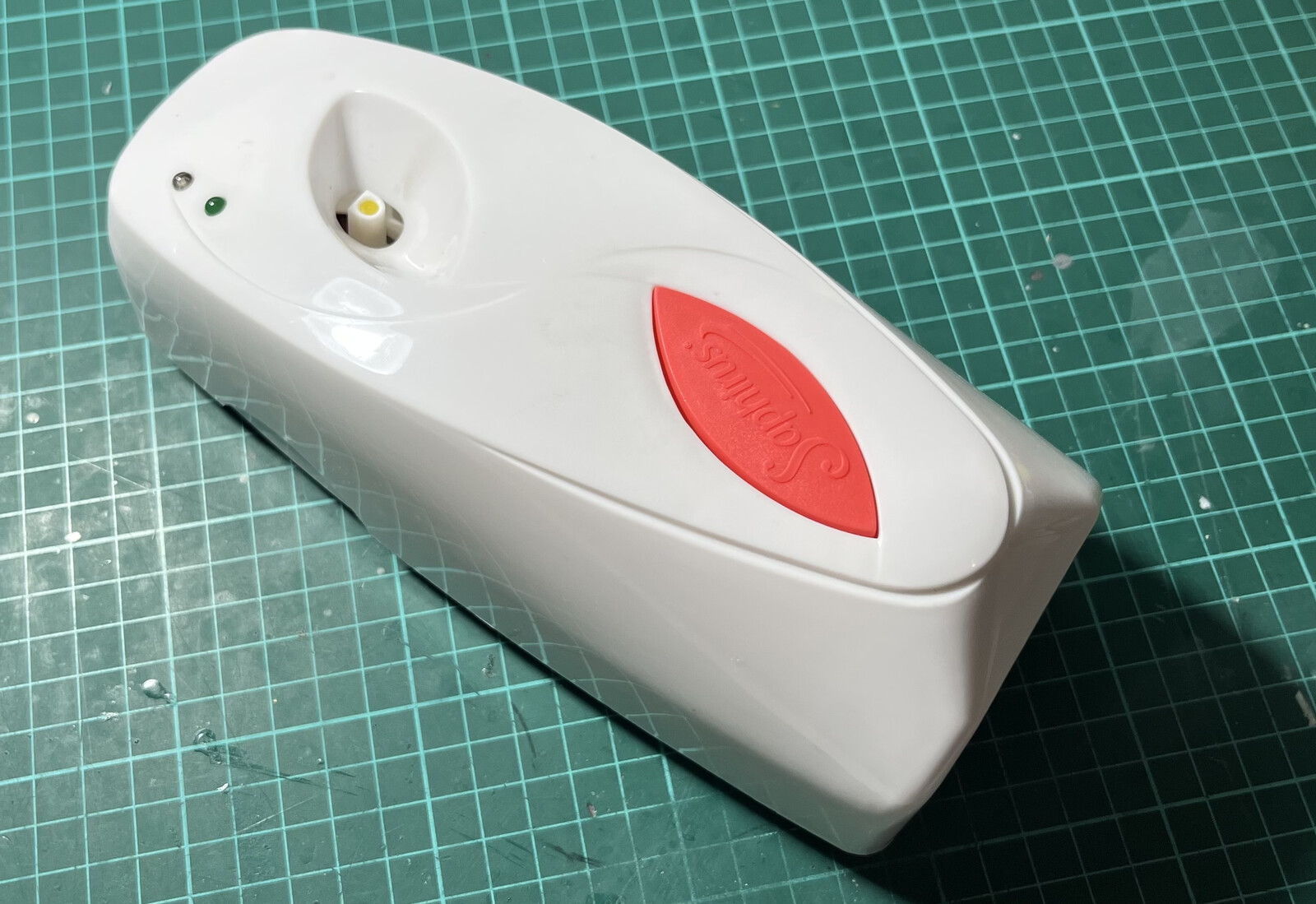
20 Feb 2025As a disclaimer, I didn’t have any real reason to do this, but I found it fascinating. These automatic air fresheners come in different forms, colors, and sizes. Still, the internals are almost always the same: An LED indicating the spray was triggered, an IR led to sense light in the room, the motor with some gears that push the lever of the can, and a PCB with two switches: one selects whether the air freshener should work during light time or 24 hours and the other determines the intervals. The PCB is offered in different flavors; mine has SMD components.
Introduction
I have at least two problems with this: It uses two AA batteries, and I hate needing to replace or recharge them occasionally. I cannot know when the spray can be running almost empty, except I am there seeing that the air freshener doesn’t spray at all. To solve the first problem, I installed a AMS1117-3.3 voltage regulator, then wired an old 5v phone charger to the air freshener.
A more sophisticated approach is required to solve the latter. Let’s tear down the air freshener first.
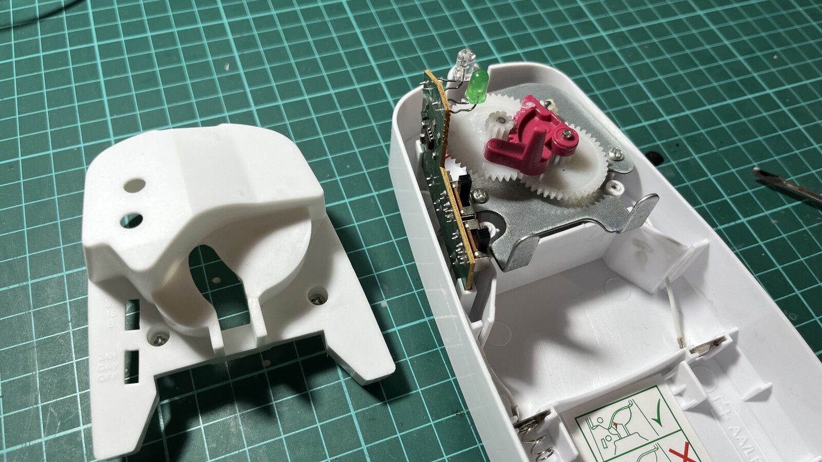
Hardware
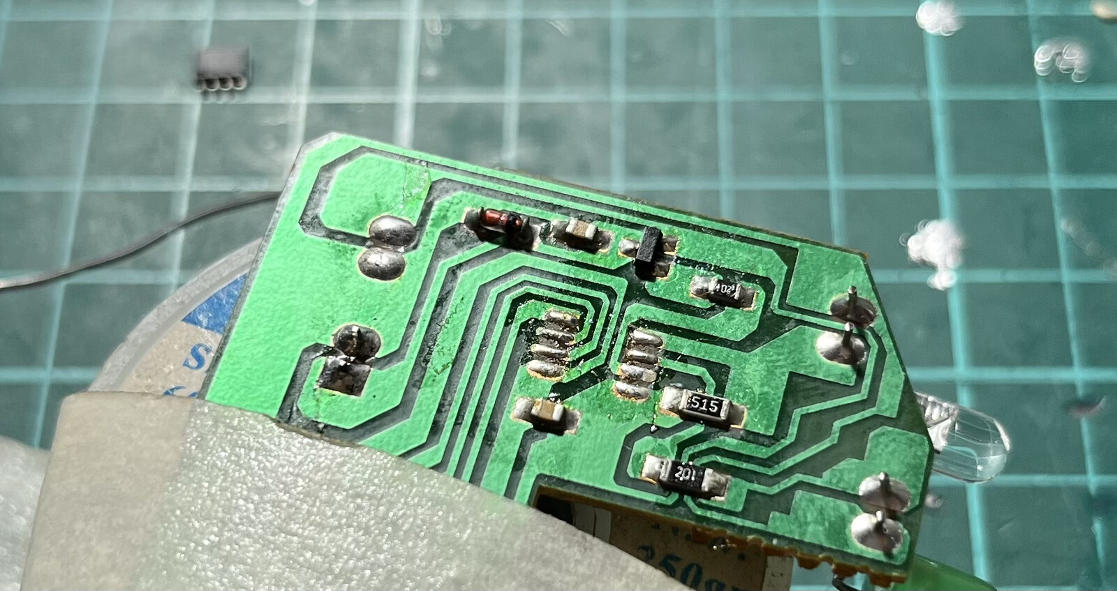
A small PCB controls everything. Looking on the Internet, I found some projects that reversed this board, but unfortunately, none of those were compatible with my board and connections. As time passed, the manufacturer replaced some of the components and their locations.
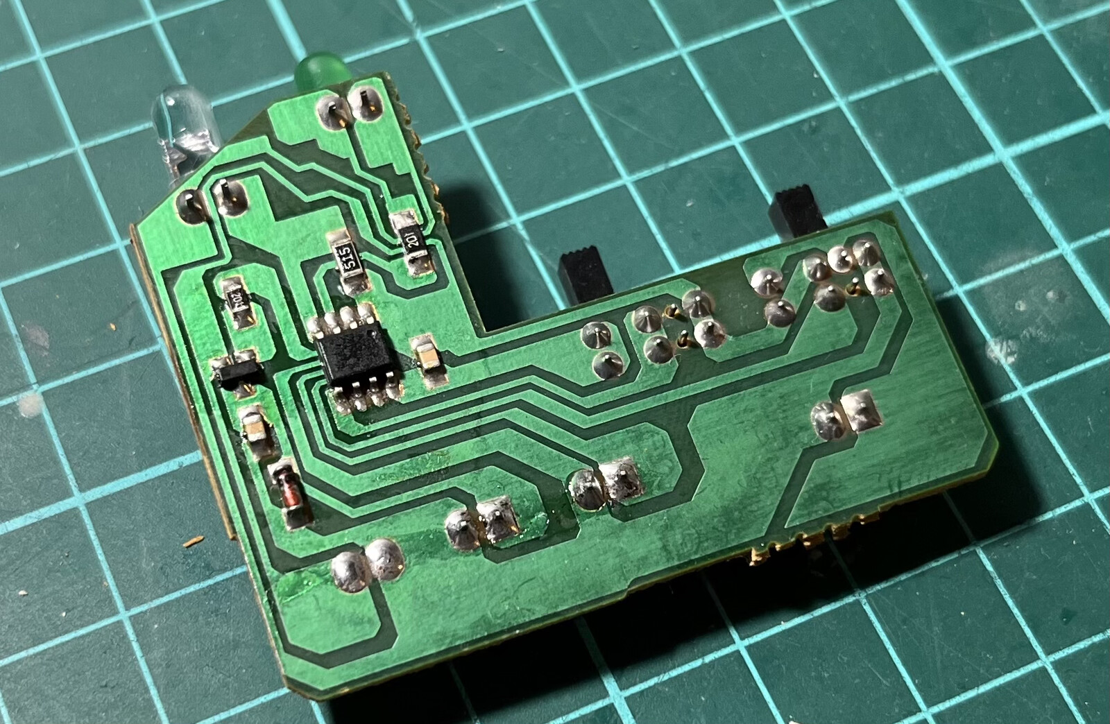
The integrated circuit is unknown, but I drew a simple schematic with interesting parts. Since I will not be using the switches installed in front, I avoided routing those connections and concentrated just on the motor, led, and infrared led.
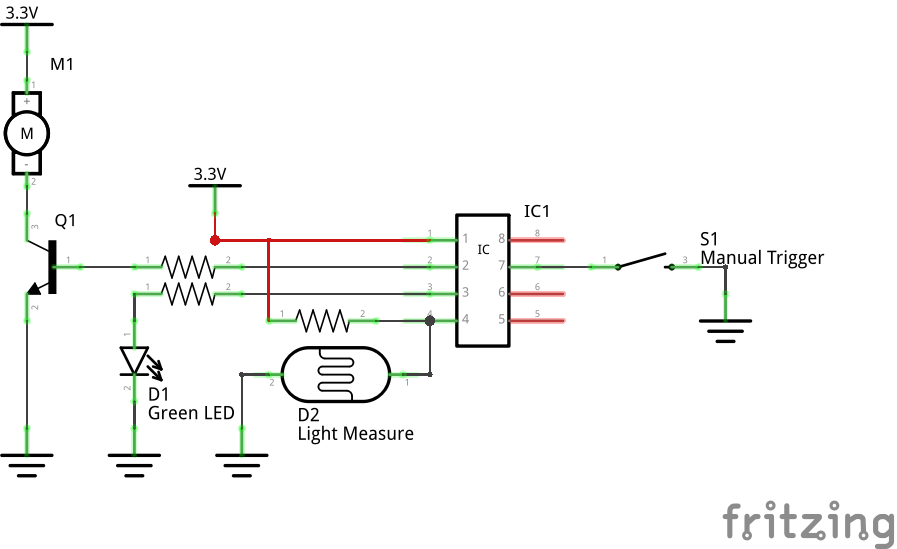
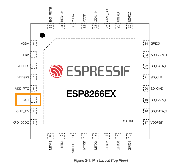
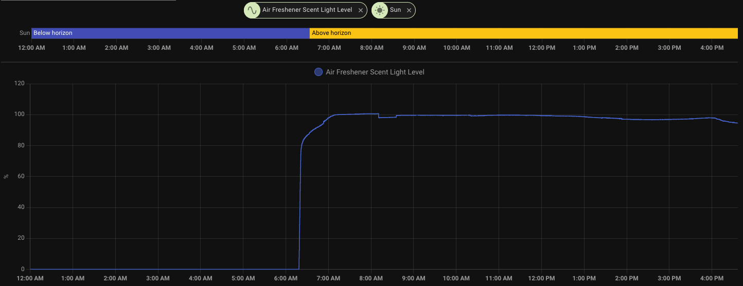
While the light sensor is not strictly necessary for my use, it would be a great idea to hack into the ESP-01 integrated (but not exposed) ADC pin, TOUT. Pin 6 is a 0-1v analog input that you can use to measure analog voltages, perfect for our light sensor. The sensor is not linear; rather, it acts almost as a switch whenever there is some light. You’ll need some good soldering skills to reach that pin, check this video for a practical demonstration.
Now, let’s map how we would connect everything. Since I/O pins in the ESP-01 are scarce, and some of those pins may conflict with TX/RX operations, it is a good idea to burn the initial ESPHome firmware into the ESP-01 before connecting it to the air freshener board. You will also need to connect 3.3v power and ground to the ESP-01 too.
| ESP-01 pin | Air freshener IC pin | Usage |
|---|---|---|
| GPIO 0 | 6 | Manual trigger |
| GPIO 1 (TX) | 3 | Green LED |
| GPIO 3 (RX) | 2 | Motor (Transistor) |
| 6 (TOUT) | 4 | Light sensor |
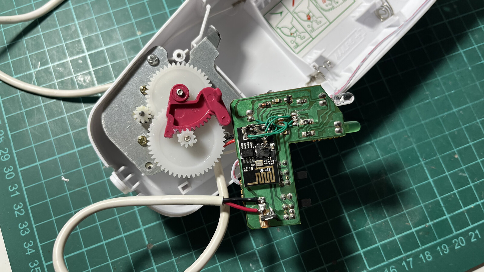
Here’s how I installed the ESP-01 on top of the original air freshener board:
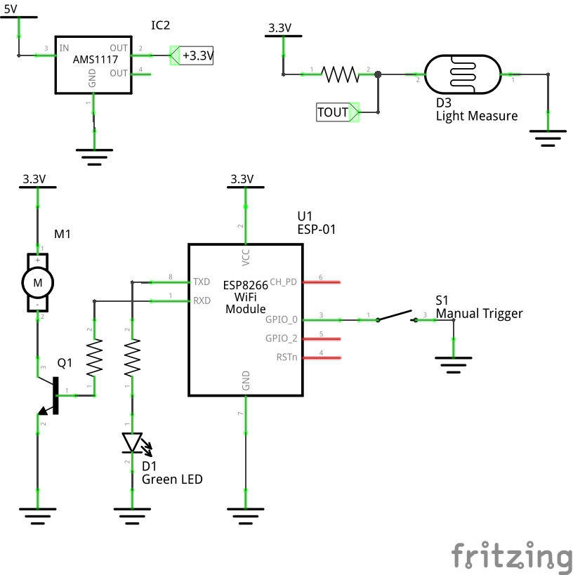
And the final schematic:
Software
The code for the ESP-01 is straightforward. I wanted a few delighters now that I have more control, so I implemented the following:
- The logger is disabled, so we can use the TX/RX pins on the ESP-01 board.
- Manual trigger from the Home Assistant dashboard.
- Manual trigger from the built-in button in the air freshener.
- The spray count is stored in the ESP-01 EEPROM.
- Spray can lifetime, considering that it lasts for around 3200 shoots.
- A Home Assistant button to reset the activation count, useful when replacing the spray can.
You may need to play with the light sensor calibration to get something reasonable. In my experience, those values work great to detect the first rays of light in the morning.
esphome:
  name: air-freshener
  friendly_name: Air Freshener
  on_boot:
    priority: 100
    then:
      - lambda: |-
          ESP_LOGD("boot", "Restored scent activation count: %d", id(scent_activation_count));
          id(scent_count_sensor).publish_state(id(scent_activation_count));

esp8266:
  board: esp01_1m
  restore_from_flash: true

preferences:
  flash_write_interval: 10min

# Disable logging to liberate RX/TX pins
logger:
  level: DEBUG
  baud_rate: 0

# Enable Home Assistant API
api:
  encryption:
    key: "your-key"

ota:
  password: "your-password"
  platform: esphome

wifi:
  networks:
    - ssid: !secret wifi_ssid_iot
      password: !secret wifi_password_iot
    - ssid: !secret wifi_ssid
      password: !secret wifi_password

globals:
  - id: scent_activation_count
    type: int
    restore_value: yes
    initial_value: '0'

# Make the internal counter persist immediately when changed
button:
  - platform: template
    name: "Press scent"
    id: press_scent
    on_press:
      then:
        - output.turn_on: motor_scent_output
        - output.turn_on: led_output
        - lambda: |-
            id(scent_activation_count) += 1;
            id(scent_count_sensor).publish_state(id(scent_activation_count));
            // Force an immediate save to flash
            global_preferences->sync();
        - delay: 1s
        - output.turn_off: motor_scent_output
        - output.turn_off: led_output

  # Reset counter button
  - platform: template
    name: "Reset Scent Counter"
    on_press:
      - lambda: |-
          id(scent_activation_count) = 0;
          id(scent_count_sensor).publish_state(0);
          // Force an immediate save to flash
          global_preferences->sync();

output:
  - platform: gpio
    pin:
      number: GPIO3
      mode: OUTPUT
      inverted: true
    id: motor_scent_output

  - platform: gpio
    pin:
      number: GPIO1
      mode: OUTPUT
      inverted: false
    id: led_output

sensor:
  - platform: adc
    pin: A0
    name: "Scent Light Level"
    update_interval: 5s
    filters:
      - calibrate_linear:
          - 1.0 -> 0.0
          - 0.02 -> 100.0
    unit_of_measurement: "%"

  # Counter as a sensor (read-only)
  - platform: template
    name: "Scent Activation Count"
    id: scent_count_sensor
    accuracy_decimals: 0
    unit_of_measurement: "activations"
    lambda: 'return id(scent_activation_count);'
    update_interval: 5s

  - platform: template
    name: "Scent Can Remaining Percent"
    id: remaining_percentage_sensor
    accuracy_decimals: 1
    unit_of_measurement: "%"
    lambda: |-
      int total_capacity = 3200;
      int used = id(scent_activation_count);
      float percentage = (float)(total_capacity - used) / total_capacity * 100.0;
      // Prevent negative values if counter exceeds capacity
      return percentage > 0 ? percentage : 0;
    update_interval: 5s

binary_sensor:
  - platform: gpio
    pin:
      number: GPIO0
      mode: INPUT_PULLUP
      inverted: true
    name: "Trigger Scent"
    id: trigger_button
    on_press:
      - button.press: press_scent
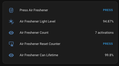
The card may look like this in Home Assistant:
Conclusion
This was a delightful project with little counterbacks. The biggest problem was realizing I had to disable the logger in ESPHome so I could use the TX and RX pins freely. Otherwise, when those pins operate as the logging interfaces, the motor may trigger, probably freezing the ESP-01 operation.
Also, discovering the ADC pin in the ESP-01 a while ago made me love this inexpensive and small chip even more.